Defining the machining strategy of mill operations
The definition of many parameters, which define the machining strategy for a model, can be performed in the < Operation parameters > window on the < Strategy > page. The window for altering these parameters is opened by pressing the < Parameters > button. This page gives access to a variety of fields and their explanatory graphics. Depending on the type of operation selected, the number of available parameters may vary. Any of the fields can be used for calculations; the user can enter any mathematical expression e.g. "10*sin(45)". To view the calculation result, it is necessary to point the mouse at the required field. The result will be shown in the tool tip text.
The following parameters can be defined on the page:
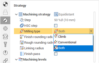
< Type of milling > can be assigned in almost all operations, except for the curve machining operations. This allows the user to control the required milling type (climb or conventional) during the toolpath calculation process.
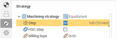
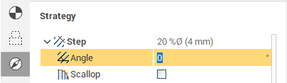
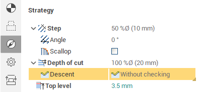
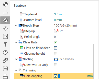
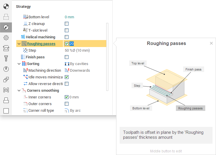
< Step > of machining defines the distance between successive depths of the tool for the plane, drive and combined operations . The step can be either assigned by as an absolute value, as a percentage of the tool diameter or calculated at every step relative to the required scallop height .
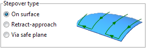
< Stepover type > defines the toolpath when moving from one machining pass to the next.
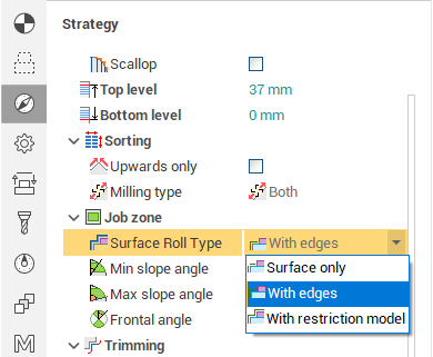
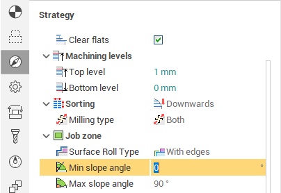
< Roll type > defines the necessity of avoiding peaks and edges of the model when machining using the volume machining finishing operations .
< Surface slope > in the volume machining finishing operations limits the surfaces being machined depending on their slope angle.
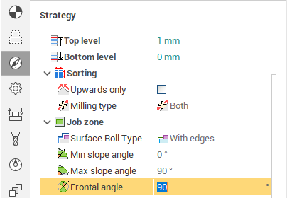
< Frontal angle > in the plane and drive finishing operations limits the surfaces being machined depending on the angle between the cutting tools face in the cut direction, and the models surface(s).
< Angle > assigns the cut angle direction for the plane operations .
< Descent type > defines the tool descent strategy for the plane and drive roughing operations.
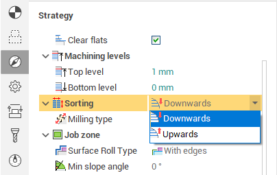
< Machining direction > during the finish machining by depths defines the machining sequence, either upwards or downwards.
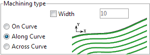
< Machining type > in the drive operations defines the strategy for the work passes formed either along or across the drive curves.
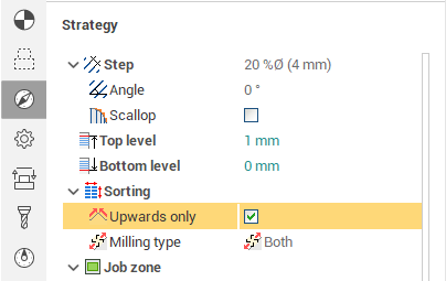
< Upward only > in the plane and drive finishing operations restricts tool movements on the model to the upward (Z+) direction.
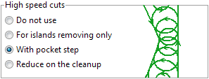
< High speed cuts > allows to reduce the NC data much in comparison with the trochoid and at the same time secure the tool.
< The corner-smoothing mode > virtually is in most operations, and provides toolpath 'rounding' when machining inner corners. This lessens vibrations and increases the machining speed.
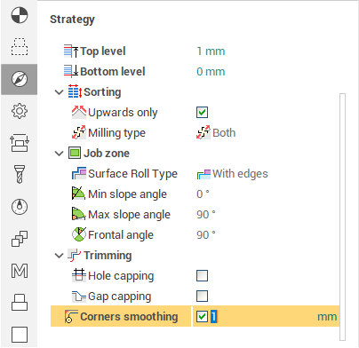
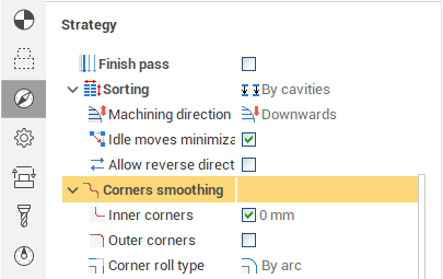
< Corners smoothing > for 2D contouring provides toolpath 'rounding' when machining inner and outer corners.
< Hole capping > in the volume machining operations , this allows the system to ignore holes in the model that have a size that is less than the defined size, leaving them for further machining.
< The allow 3D toolpath > mode allows the system to create a 3D toolpath for material removal in all areas that are not accessible for machining on the current level (e.g. inner corners).
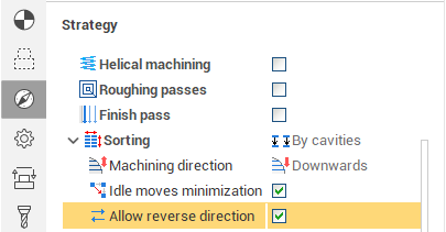
< Allow reverse direction > in the curve machining operations allows the tool to reverse its cut direction along a curve if it will decrease the overall amount of tool movements.
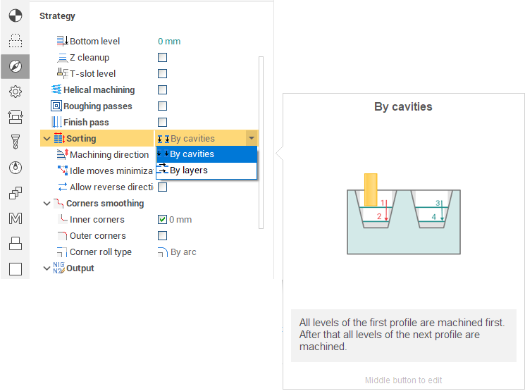
< Machining order > defines the machining sequence in the curve machining operations (by contours, by depth).
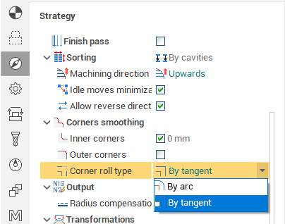
< Corner roll type > defines the outer corner angle bypassing method in the curve machining operations .
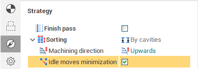
With < Idling minimization > active, the total distance that the tool moves for machining all selected curves, is kept to the minimum. Otherwise, the machining will be performed according to the order defined on the Model page .
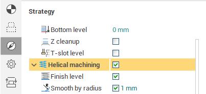
< Helical machining > allows the user to obtain a spiral-like toolpath when machining a 2D curve .
< Roughing XY paths > allows the use of several XY passes to remove the stock material instead of a single pass. This can improve the surface finish by reducing the load on the tool.
< XY cleanup allows > the user to obtain a higher quality surface finish by leaving only a small user defined stock for an automatic finish cut.
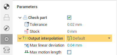
< Work passes interpolation > approximate toolpath by arcs.
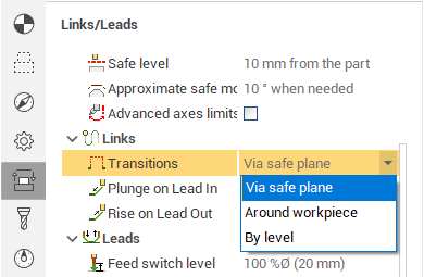
< Transition > allow select stepover method for curve machining operation.
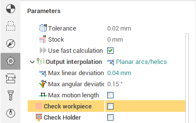
< Check geometry > for finishing operations. This operations not check rest material by default and machining all surfaces from job assignment. For skip already machining patches you must set check < Check workpiece > or < Check part > and setup thickness value.
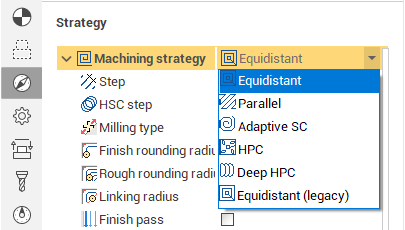
< Machining strategy > allows the user to obtain a parallel-like or equidistant-like toolpath when machining for pocketing operations.
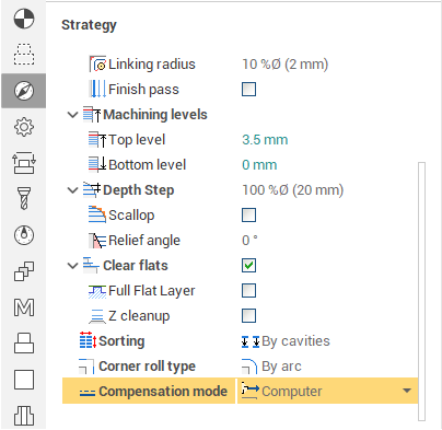
Tool < compensation > is available for pocketing operations.
The strategy of flat land machining on axis Z.
In < Flat lands finishing > and < 2.5D flat land > operations the strategy of removal of a material layer above a horizontal plane is defined in panels: < Plunge Height >, < Machine by Layer >, < Z cleanup >.
< Machine By Layer > The material may be deleted for some passes. For this purpose, it is necessary to switch on < Machine by Layer >.
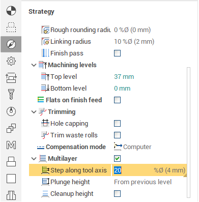
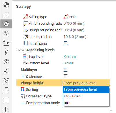
< Plunge Height > The height of the layer is set in the < Plunge Height > panel; in particular, it defines a value of level Z on which the given type of plunge will join.
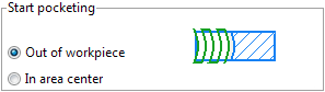
< Start Pocketing > In the panel is defined the strategy of the tool motion within the limits of one layer.
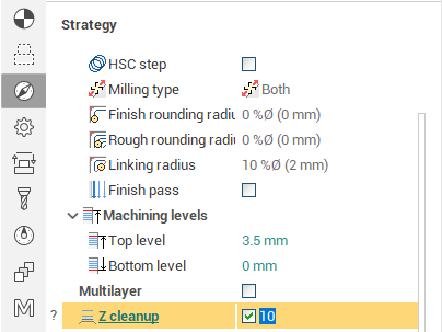
< Z cleanup > For the definition of width machined material layer on finish pass, it is necessary to switch on the < Z cleanup > option and to enter a stock value on finish pass.
On the < Strategy > page in the < Operation parameters > window for the hole machining operation the user can define the cycle type for hole machining (drilling, boring, tapping etc.) and its parameters. The set of parameters depends on the cycle type. Points for drilling can be defined in the < Model > window, or be automatically imported from a corresponding roughing operation. All holes for an operation are machined using one tool and a single cycle type. To machine holes using different cycles it is necessary to create a new operation for each cycle type. The order of hole machining can be defined either by the list, defined on the < Model > page, or be optimized so that total tool movements between holes is minimal.
See also: