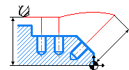
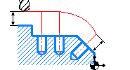
Hole machining operation
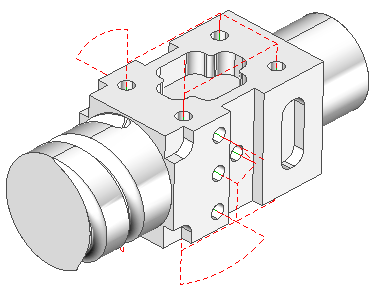
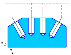
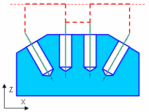
The hole machining operations are designed for drilling, centering, boring, countersinking, tapping, thread milling and hole pocketing. It can machine holes that are not lying in the same plane and that are not lying in orthogonal planes. The operation can be used both for the machining of holes in a model, or for pre-drilling of the tool plunge points for the pocketing and waterline roughingwaterline roughing operations. For this, the system will use either user defined drill points, or points generated automatically by the waterline operations. The list of holes can also be created automatically from a geometrical model using the holes recognition function.
For drilling the tool plunge points during pocketing and waterline-roughing operations it is necessary that when creating a hole machining operation the user define the operation prototype for which to perform the pre-drilling. The prototype operation will contain the list of drilling points and their depth for the hole machining operation.
Holes can be automatically recognized, selected and added through graphic interface, specified by center points or by manual coordinate input. Coordinates for holes centers are assigned by points, which can be imported from files or defined in the 2D geometry mode. The list of points with their parameters (Z rapid height and drilling depth) is formed in the Job assignment window. In the same window the user can access the function of automatic recognition of holes in the model.
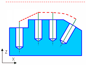
The hole top level and bottom level for every point can be assigned by the user or calculated automatically. When the top level is calculated automatically, it will be determined according to the workpiece model, and the bottom level definition based on the model being machined.
In most cases the diameter of the tool should be defined equal to the diameter of holes. And when machining holes by spiral and circular strategies, the diameter of the tool should be smaller than the hole diameter. All holes of an operation are machined using one tool and one cycle. To machine holes of different diameter or different types of cycles one should create several operations. Excluded from this are the spiral and circular machining options.
You can use the operation properties inspector to setup general operation parameters.
Hole machining mode and other additional parameters are set on the Strategy tab.
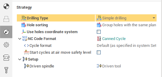
The dialog interface and parameter list change according to selected <Drilling type> option.
The order of the holes machining depends on the order in the job assignment list if the Holes sorting is set to By list. if Optimal is selected then the system minimizes the length of the idle motions. If Group holes with the same plane item selected then system will optimize machining order inside groups of holes that lie at the same planes.
If Use holes coordinate system is off then alll holes machined in the operation's Workpiece coordinate system (G54 – G59) or Local coordinate system. If Use holes coordinate system is on then the ORIGIN command is output before the each hole machining (or before each hole with changed plane). So every hole is machined with it's own local coordinate system. Read the operation coordinate system topic for detailed information about ORIGIN. So the hole machining cycle is applied for the XY plane. Most of the CNC supports the cycles in this plane.
NC code format defines the way of the g-code output:
Long Hang. All motions are output as the elementary movement commands (lines and circle arcs). Use this option for special cases then machine's CNC-system can't form canned cycle movements (for example, some CNC-systems do not support canned cycles at non-orthogonal planes).
Canned cycle. The cycles is output. Every cycle contains a full set of motions to machine the hole within itself. The way of machining depends on the used CNC. See your CNC manual for the detailed information.
For compatibility with older versions of postprocessors the Cycle format property provides the ability to change the output format of the drilling cycle (when Canned cycle output method is used). It can have the following values.
Default (as specified in system Setup). The cycle format will be used, which is specified in the system settings. The default setting in the system Setup window has a value EXTCYCLE.
EXTCYCLE (recommended). The new format of the cycle EXTCYCLE will be used. This cycle has an advanced set of parameters, including all machining strategies that are implemented in the system, and allows a realistic simulation of the tool movements according to the chosen strategy.
CYCLE (for old postprocessors). The old format of the cycle CYCLE will be used. This cycle cannot be used for some of the strategies available in the system (e.g., hole pocketing or machining by spiral). Also this cycle simulates any machining strategy only as a simple movement to the lower level of the hole. This format is required for compatibility with older versions of postprocessors, where EXTCYCLE technological command handler is not implemented.
The Start cycle at air move safety level option defines the position at which the each cycle toolpath will start. If it is disabled the the first cycle point located at the Rapid distance from the top level of hole. If it is enabled then the first cycle point is at the air move safety level which depends on the part top level or origin of CS. It can help you to reduce the number of intermediate link points when you want to have the modal cycles output mode at the each next movement (whithout redundant G80 cycle off commands).
At the Links/Leads page you can flexibly adjust transitions between holes.
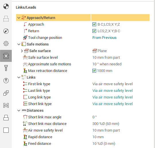
Using the First link type, Last link type, Long link type and Short link type parameters you can choose an appropriate way of transition separately for each case. There are the following values.
Via safe surface. The toolpath continues until the hole axis intersects with the specified safe surface (plane, cylinder or sphere). If the intersection point goes far beyond the dimensions of the part, then outside the gabarites, the point is projected onto the safe surface at the nearest distance. You can explicitly set the Max retraction distance from the first cycle point.
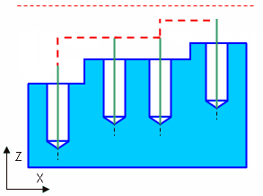
Via air move safety level. The toolpath continues along the hole axis up to the air move safety level. The air move safety level can be definied as absolute distance from the origin of CS or incrementally from the part (plus workpiece and fixtures) top level.
Absolute safe level
Incremental safe level
Straight. Straight transition between holes' first cycle points (which are either at rapid distance a or at air move safety level depend on Start cycle at air move safety level option).
Orthogonal. The same as the Straight transition but one intermediate orthogonal point appears if the holes are on different height.
Using the Short link max distance and the Short link max angle parameters you can divide the long and short transition cases to be possible to make diferent type of links.
The Feed distance dimension defines the point on the hole's axis from the upper level of the hole on which the feedrate is switched from the rapid to the work one. So this distance is used to avoid the collision on the rapid feed.
The Rapid distance defines the point on the holes axis in which the cycle should start. The tool will go to this point at rapid feed. If the Start cycle at air move safety level option is enabled then this point is extended to the air move safety level.
For the spiral (thread milling) and hole pocketing cycles it is possible to generate the g-code with the radius compensation. The radius compensation works like in other operations.
Use Feeds/Speeds tab to setup cutting conditions: spindle revolution rate, cooling, feed rates for different motion modes(approach, retract, work feed and the like). Auxiliary transitions (non-cut transitions) are performed either with rapid feed rate or with work feed rate, this option is controlled by the All non-cut feeds as rapid check-box. Work feed rate motion for non-cut transitions is useful then machining non-orthogonal plane holes as some NC-systems control only the start and end positions of the tool when performing rapid motions.
Multiply tool path by axis simplifies the machining of the repeated part holes. It works like in other operation.
See also:
Operation for 2/2.5-axes milling
The ways of the holes machining