Stepover method
<Tool stepover> is a tool movement between the contours being machined. One should not mistake it with the machining term <Stepover>.
If the model is machined using one tool, and the machining toolpath represents by itself a tool transition along several contours, then it is necessary to create machining conditions for the transition from one contour to another.
In volume machining operations the step-over from one work pass to another are performed by the following methods:
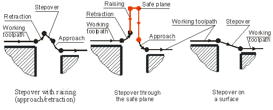
<On surface>. Tool stepover is performed without retracting from the model being machined. With the small distance between the end points and beginning of the neighboring work passes, shorter machining times are achieved;
<Retract-approach>. At the end point of the work pass there will be a retraction using the defined method, then a stepover at the work feed to the first point of the next approach, then the approach according to the defined method to the first point of the next work pass. Such a stepover takes more time, but the stepover is performed without touching the machined surface;
<Via safe plane>. In the end point of a work pass there will be a retraction using the defined method. Then the tool will rapid to the safe plane. Stepover at rapid feed at the safe plane. Then, tool lowering and approach according to the defined approach method;
Because the step-over methods <On surface> and with <Retract-approach> are the optimal only with the short length stepover, if it is necessary to perform a stepover of a longer length, then regardless of the defined stepover type, the system will automatically generate a stepover via the safe plane.
In the curve machining operations, SprutCAM X gives the user the following step-over methods:
<Via safe plane>
<Tool step-over around the workpiece and at the defined Z height>
<By Z>
<Around workpiece>
Via safe plane
This method is the most frequently used one; but it is not the optimum relative to the machining complexity. The safe level can be assigned in the <Operation parameters> window on the <Parameters> page. Stepover is normally performed at the rapid feed (G00).
Tool step-over around the workpiece and at the defined Z height
If on the machining <Strategy> page, the user does not activate the Idling minimization mode, then the contour machining order will be defined by the order in which the contours are located in the list of the <Model> page. To define an optimized sequence of contour machining using the minimum length of idle moves, the user should select Idling minimization mode on the machining <Strategy> page.
SprutCAM X in the 2D machining mode allows the user to work either using or not using a workpiece. If a workpiece is not used, then the stepovers between work contours will be performed either by the safe plane, or at the defined Z level.
Using a workpiece will provide a safer work mode because the system will automatically create a step-over toolpath with control of tool collision with the workpiece, also in this case, SprutCAM X will give the user more possibilities to optimize the machining toolpath.
The workpiece can be defined on the <Model> page. For a complete description on how to create a workpiece, refer Workpiece.
By Z
The plane level for transitions can be assigned on the machining <Strategy> page relative to the zero of the current coordinate system.
Around workpiece
The toolpath will be created using the shortest route around the workpiece profile on the plane of the work contours location. To assign the feed, in the <Feedrate> page the user should choose the Feed to next mode and in the feed value assignment window define the required value. The workpiece must be defined.
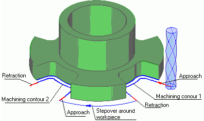
The step-over toolpath depends on the workpiece shape and will be formed as a curve around the workpiece area that is found. The shape of the step-over curve is also affected by the distance from the workpiece to retraction and approach points to contours.
An example of toolpath alteration, depending on the value of that figure (h) is shown in these pictures. The toolpath can change its look from a straight line to the curve that repeats the shape of the workpiece as shown on the picture. Concave areas of the workpiece pass along the shortest curve, convex – along the rounding one.
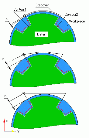
The step-over curve is constructed touching the edge of the tool against the workpiece, therefore in practice, when assigning a workpiece; the user should add an additional stock to the workpiece on the <Model> page.
In order to obtain the desired step-over curve the user should use different values of h for the approach and retraction points, and also alter the workpiece profile.
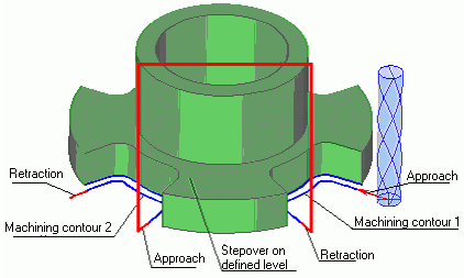
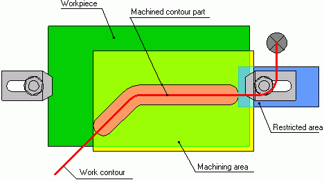
One should pay special attention to the case where the contour has areas that go beyond the workpiece area. In SprutCAM X there is a rule – if a workpiece has been defined, the machining toolpath will be formed within the workpiece area only. If machining and restricted areas have also been defined, then the toolpath will be formed within the workpiece area, inside the available machining areas and outside the restricted areas (see pic.).
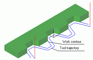
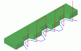
In the picture the toolpath is formed regardless of a workpiece, using the activation and deactivation area of compensation by tangent. As can be seen in the picture, the toolpath is formed equidistant to the work contour:
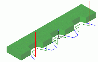
With a workpiece (bar) defined. The toolpath has been formed regarding the workpiece, i.e. within the workpiece area. Outside of the workpiece, machining will not be performed. To every area the system has automatically added the compensation activation and deactivation areas. Tool transition from area to area is performed at the safe plane:
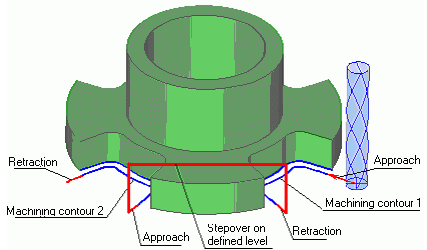
This operation has the same parameters as the previous one; the difference is in step-overs. This operation uses step-over at the defined level:
In this operation, the system uses step-over round the workpiece. One should note that the compensation activation and deactivation blocks will automatically be added to the corresponding areas of the work contour: