Assigning parameters of mill operations
The main parameters for the current operation can be defined in the < Operation parameters > window. It opens when the < Parameters > button is pressed.
This window have some sheets:
< Tool > – for setup tool parameters.
< Feeds > – for setup tool feeds.
< Lead-In/Lead-out > – for setup approach, engage, return, retract and plunge.
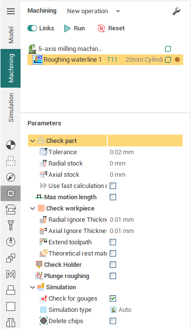
< Parameters > – for specific operation parameters setup.
< Strategy > – for operation strategy setup.
Each operation type has its own help graphic and parameter list. Depending on the type of operation selected, the number of available parameters may vary. Any of the fields can be used for calculations; the user can enter any mathematical expression. To view the calculation result, it is necessary to point the mouse at the required field; the result will be shown in the tool tip text.
The following can be defined on the < Parameters > page in the < Operation parameters > window:
<Geometrical coordinate systems> of an operation, defines the position of the workpiece and zero adjustment for the milling machine. All coordinates for the NC program will be calculated in the defined coordinate system. Any previously created coordinate system can be selected as the coordinate system for the current operation. By default, when a new operation is created, the currently active coordinate system is used.
<Rotary axis position> can be defined if there is a rotary head on the milling unit, and its position is defined in the system settings. In this case, at the beginning of every operation, the < ROTABL > command for positioning of the rotary head will be inserted into the CLDATA program. When using the rotary head, its position must be synchronized with the coordinate system for the operation. When the window is closed this condition will be verified. If it is not synchronized, then SprutCAM X will attempt to select a coordinate system that will match the defined position of the rotary head. If a suitable coordinate system is not found, then the system will suggest creation of a new coordinate system, which will correspond to the defined position of the rotary head.
<Machining levels> defines the range (depth) for machining along the Z-axis. If a tick is placed next to a field that defines the machining level, then the level displayed in the field will be used, otherwise, the dimensions of the model being machined will be used.
<Safe plane> defines the level at which rapid movements of the tool can take place.
<Deviation> defines the maximum deviation allowed for the approximated toolpath. The default machining tolerance for all operations is defined in the system settings window ( Options –> Machining tab).
<Stock> – the amount of material that is left after an operation, for further (finish) milling. By default, for finish operations the stock is set equal to 0, and for the rough is calculated by internal algorithms.
<Z Stock on> – can be defined only for the engraving and pocketing operations.
<Lateral angle> – available only in the engraving operations and defines the side surface of the model. Unlike the draft angle, this parameter is not considered when machining restricted areas.
<Z step by Z> is available in all rough operations and in the waterline roughing operation, and conforms to the thickness of the material layer, removed for each pass. By default it is calculated by the system according to the tool parameters of the operation and the workpiece dimensions. The step can be assigned in millimeters(inches), as a percentage of the tool diameter or calculated with regard to the required number of passes. When defining the step by scallop, it will be calculated for every layer according to the amount of the required scallop height.
< Clear flats >. With this function active, the system will perform additional passes at those levels, where there are horizontal areas.
< Relief angle > is available only in the waterline roughing and the engraving operations. It defines the minimal horizontal offset between the layers being machined. It is used to prevent the side of the tool touching the side of a deep-machined area.
< Draft angle > is available only in the waterline roughing and the engraving operations. It defines the minimal horizontal offset between the layers being machined. It is used to prevent the side of the tool touching the side of a deep-machined area.
<Z cleanup> with increment on the Z-axis for 2D and 3D curve machining operations. It defines the value for additional stock for a finishing pass. This gives a better surface finish and reduces cutter push off.
When the < By default > button is pressed, the system will set all values to their default state. When the < Ok > button is pressed the alterations will be applied for the operation, otherwise the operation parameters will not be changed.
See also: