What's new in SprutCAM X 17
General improvements
Application start time reduced
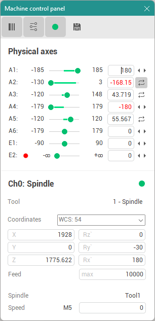
Interface - new popup dialogs design.
All window design is updated to conform to modern user interface standards and provide straightforward user experience. More examples are shown here.
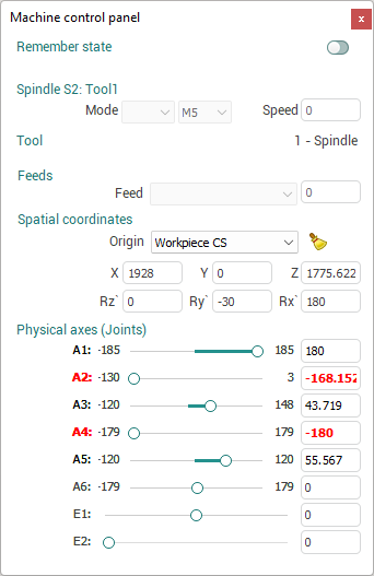
Machine control panel
Axes brakes and robot flips could now be watched using the window.
Project Snapshots
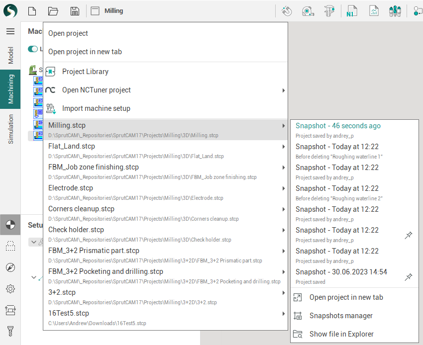
Now you can load snapshots (previously saved/autosaved versions of the project) in one click. The dropdown list of recent projects now contains a submenu where you can see the list of snapshots. You can click any item in list to load it quickly. The current snapshot is highlighted in green.
The pin button prevents automatic deletion of snapshot. The list shows only 10 snapshots. There is a separate Project snapshots manager window if you need more.
Snapshots by events
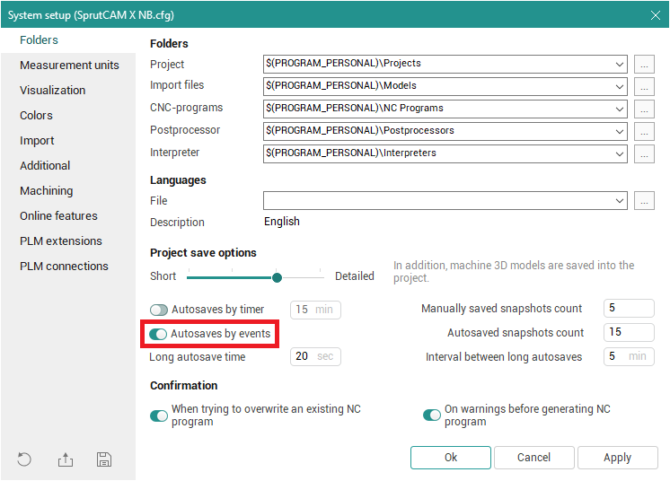
You can use Autosaves by events . In this case the system will save project during some events: before calculation run, after calculation run, before deleting operation .
New project extension - ".stcp"
The new project extension (".stcp") is used f or the new version of the system . The old ".stc" extension will also be supported.
Machine setup file to create new projects quicker
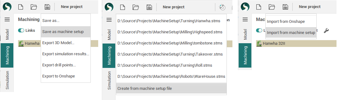
Now you can save the project as a new kind of file - machine setup file (*.stms). After that you can quickly create new projects using this file as a template. The following data are saved in the file: machine, stages, part, fixtures (including position), tools, approaches/returns, workpiece coordinate systems list, types of tool blocks, and placement in the turret. A new dropdown menu appears under the new project button where you can choose one of the recently used machine setup files. Also you can import machine setup file into the current project.
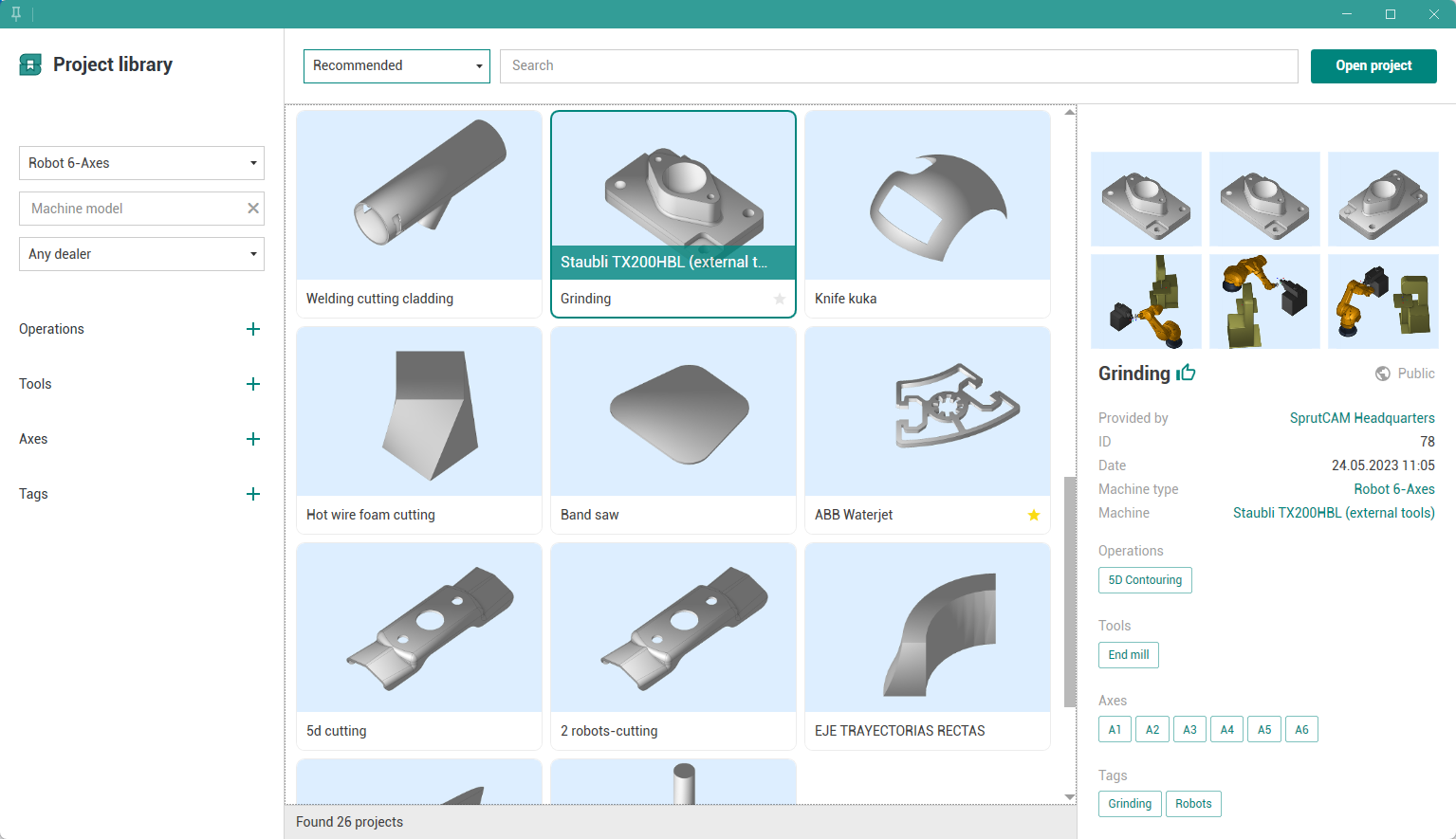
Project library
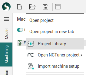
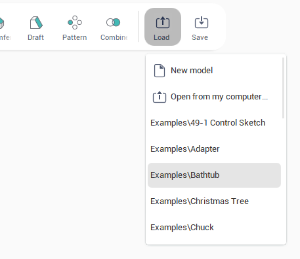
The Project Library allows to find and open example projects from our online library. Project library can be started directly form the SprutCAM X "Open" menu. More information available at this page: Project Library.
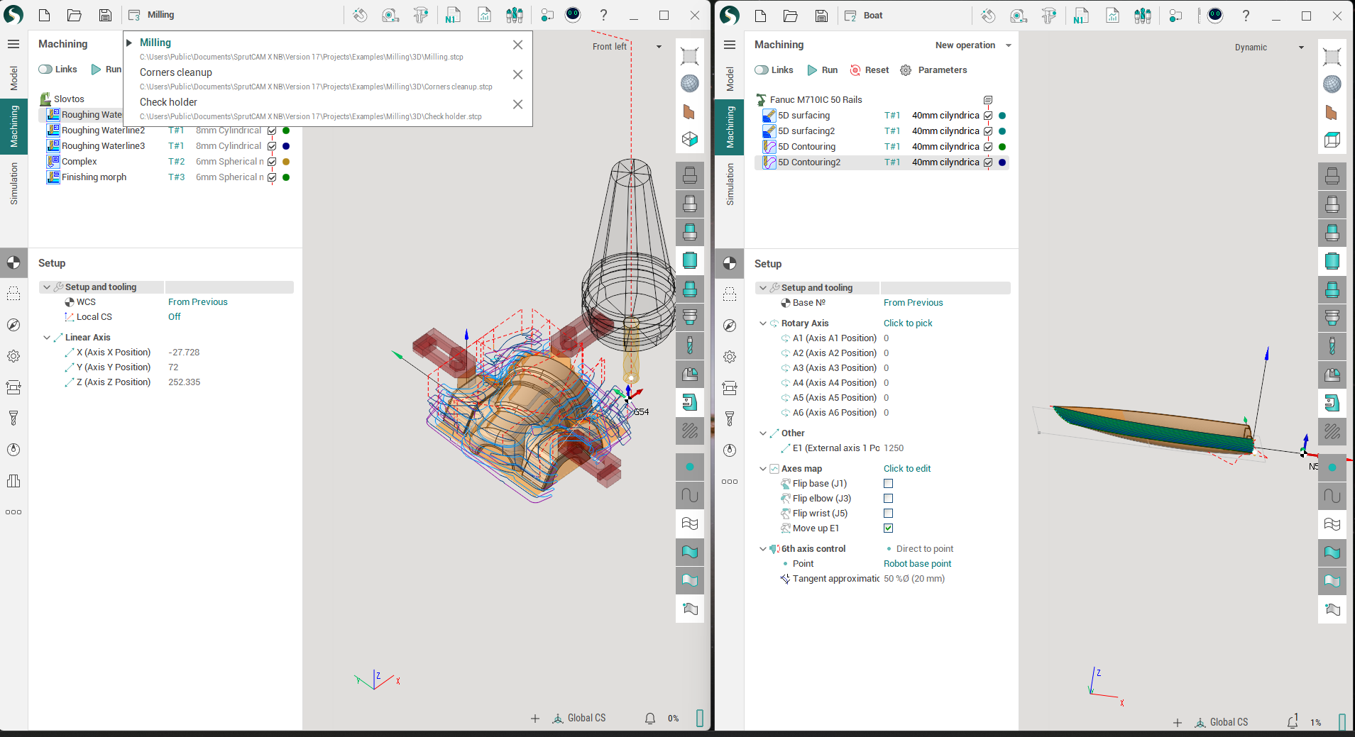
Multiproject workflow
Create or load two or more project at the same time. You can work with multiple SprutCAM X projects either using tabs to switch between them our pop-out and work with separate SprutCAM X windows.
Technology updates
Improvements in roughing waterline
|
Version 16 |
Version 17 |
|
|
|
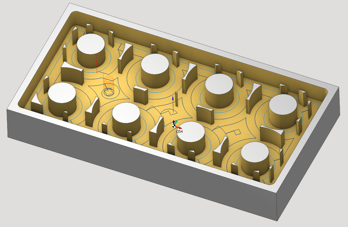
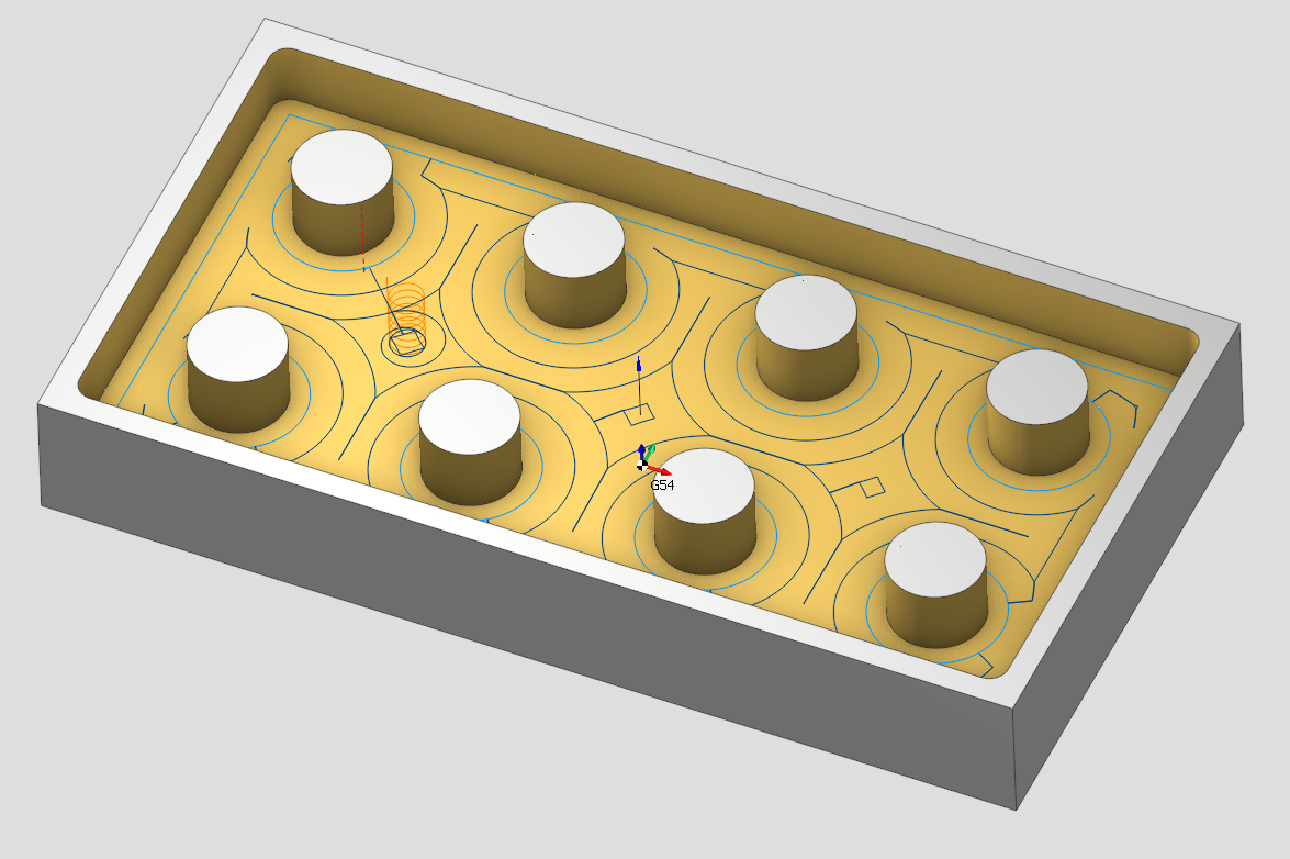
If the rough step is greater than 50% of the tool diameter, then the special tool path is generated to remove the islands. Calculation time reduced up to 40%. Simulation highlights uncorrect plunges and long link feed cutting.
Redundant axes optimizer improvements
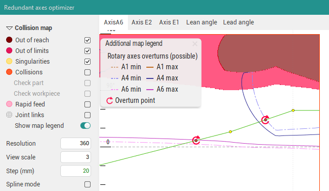
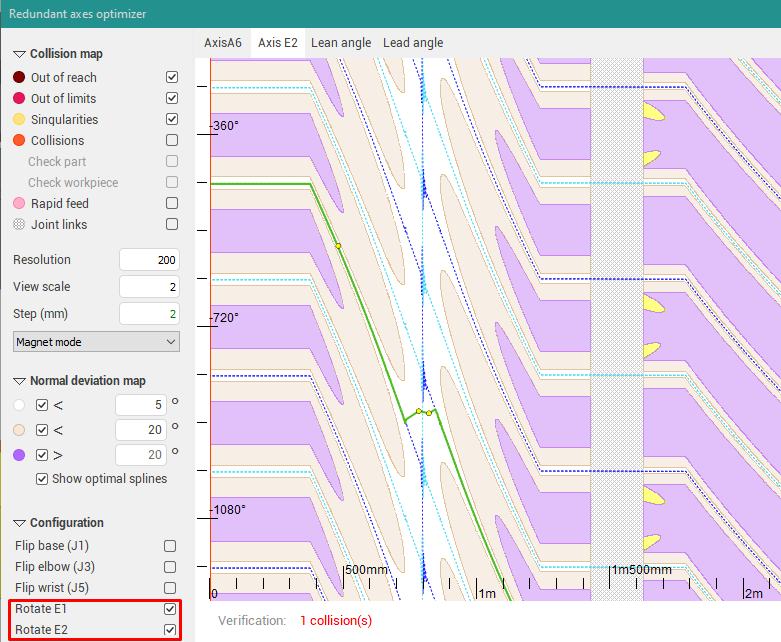
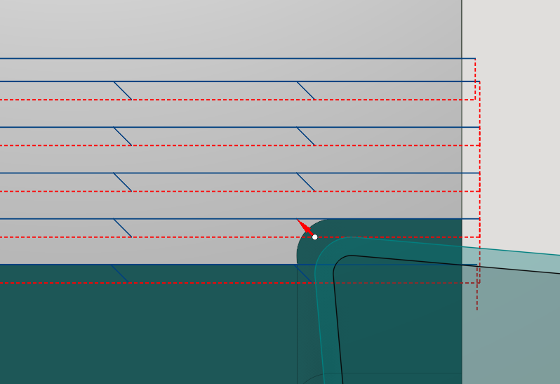
Added display of periodic rotary axes overturns
Now it is possible to use the redundant axes map to see potential problems in the toolpath, which are connected with the rotary axes overturns. Overturns happen if the rotary axis reaches one of its limits and in order to continue machining it needs to do one full rotation (360°). In previous versions no information about the overturns was available to user because, despite the overturn, the axis always stays within its limits.
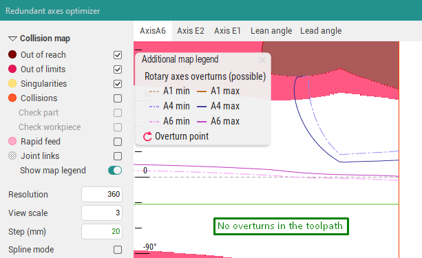
The blue and purple lines show the possible overturn locations in the toolpath in case the spline intersects with them. However the intersection doesn't always correspond to overturn; the true overturn locations are additionally highlighted as red bold points with the "overturn" sign. Also if there are overturns in the toolpath, their count is displayed in the "Verification" status bar.
The light dashed/dark solid lines show the points where the given rotary axis might reach its minimum/maximum respectively.
If you noticed the overturns in the operation's toolpath, you can try to avoid them by moving the spline so it doesn't intersect the possible overturn lines or the intersections are "fake" (the rotary axis did not reach its limit yet in this point). Also changing the robot configuration (the "Flip elbow", "Flip wrist" parameters) might also help to avoid the overturns. An example of spline editing to avoid the overturns is shown below on the screenshots.
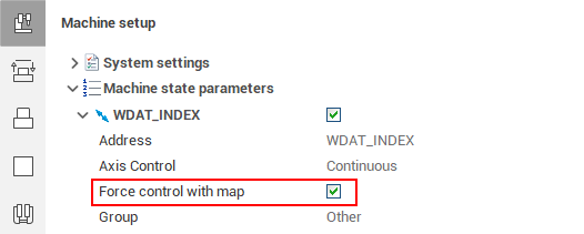
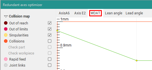
Arbitrary machine parameter control using map (optimizer)
If you need to control the changes of an arbitrary machine axis using the map, you can enable the "Force control with map" flag in the corresponding machine state parameter. After this the axis will appear in the axes map window, and, as usual, you can define parameter value in each toolpath point using spline. Also see the documentation on how to set this flag in the machine xml-file.
Singularity avoidance for the 2-axis rotary table of the robot
A special mode is activated for robots with the 2-axis rotary table and both enabled table flips. This mode is identical to the Axes map for 5-axis machines and allows you to get the rotary table trajectory without sharp changes and also as close to the geometrical toolpath as possible. More info about this feature is available in the documentation.
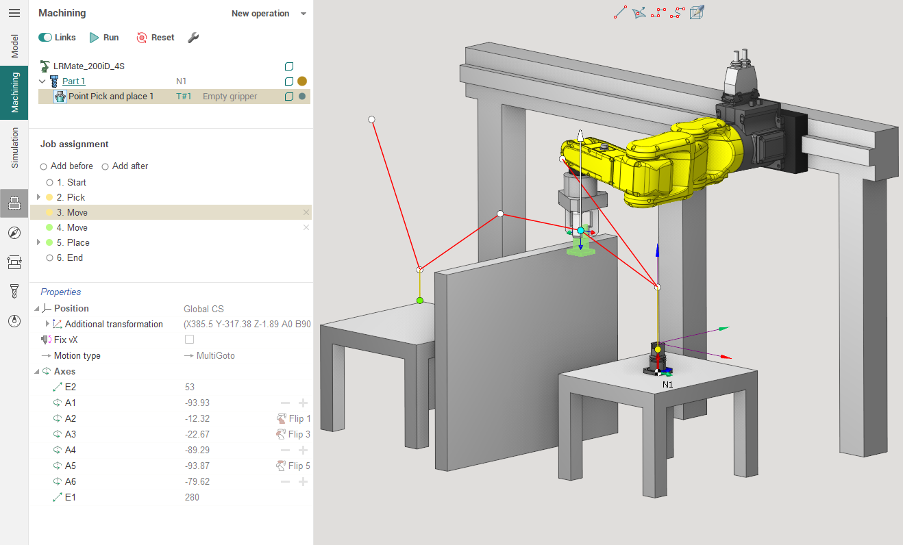
Point Pick and Place operation added
It's based on the old "Pick and Place" operation.
The operation has a new working task based on nodal points. At points, a position is set for moving the machine. By adding and removing points, you can set the desired movement of the part. See more here.
Links in basic milling operations improved
The main changes in links affected “Safe distance” and “Rounding radius” parameters. We have made a new algorithm for providing safe distance in links. It has significantly reduced excess work passes, especially, with big safe distances. Also it has reduced amount of safe motions due to replacing them with long or short links.
This changes affected 5 operations (“Pocketing”, “2.5D pocketing”, “2.5D flat land”, “Roughing waterline” and “Flat land”) and 3 strategies in them (“Equidistant”, “HPC”, “Deep HPC”). In “Adaptive SC” strategy only changes with reducing safe motions has been applied.
Scallop operation toolpath enhanced
The scallop operation toolpath has been changed. There is you can see two example images before and after trajectory improvement.
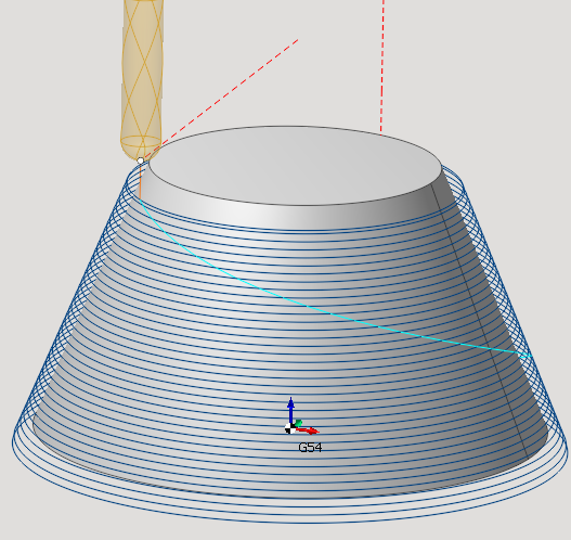
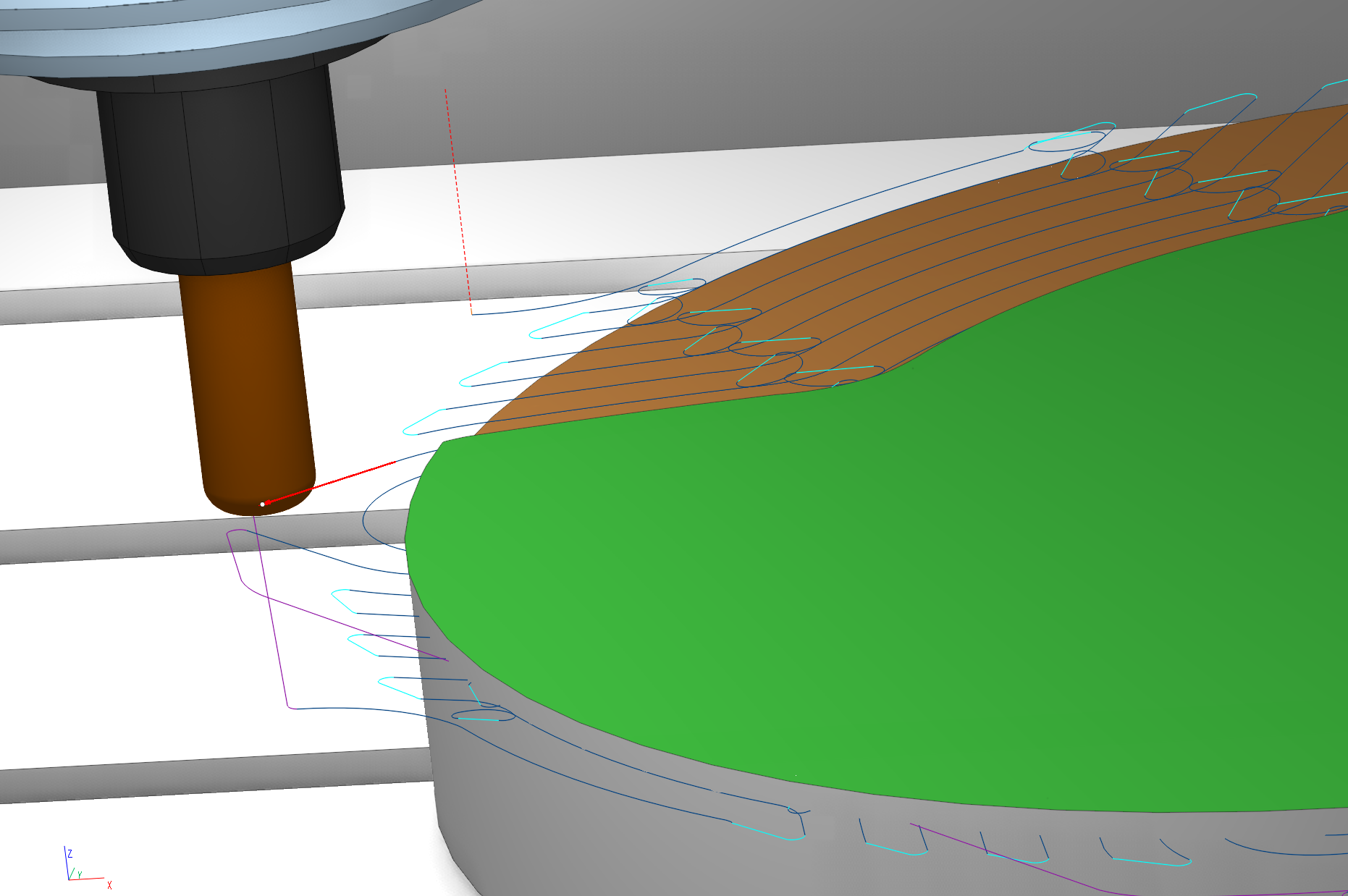
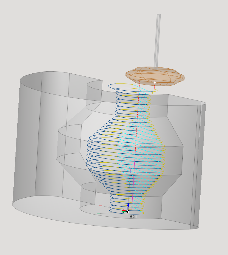
New undercut waterline operation added
Added a new "Undercut waterline" operation.
The operation allows you to create finishing and roughing undercut toolpath for supported undercut tools.
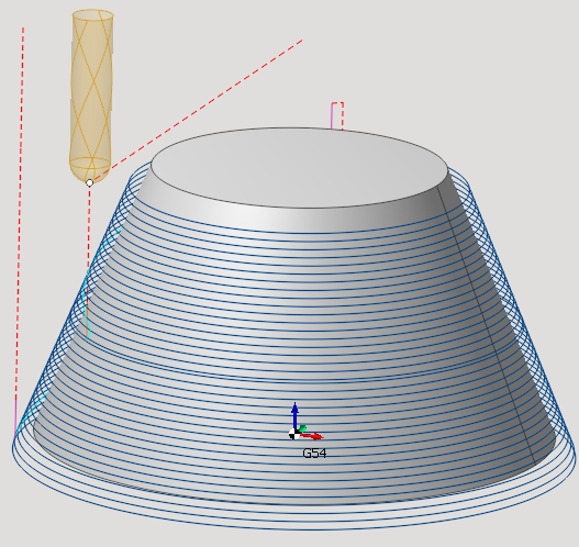
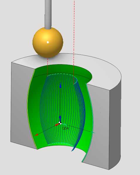
Undercut tools support in 5D Surfacing operation.
The tool only works for fixed axis.
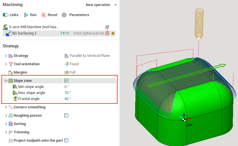
Added slope zone in 5D Surfacing operation
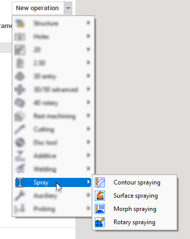
New group of operations added - Spray
For spraying, several new operations were created on the basis of existing ones in order to optimize the set of purchased options. They are all placed in the same Spray group and are licensed jointly. The following operations are currently available: Contour spraying, Surface spraying, Morph spraying, Rotary spraying.
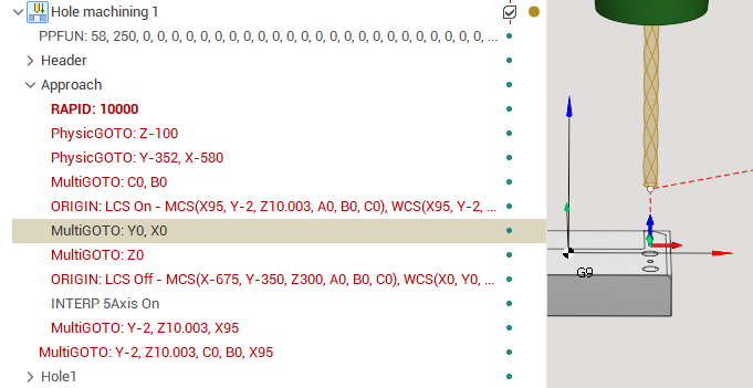
Approach/return for the TCPM enabled operations using Local CS
This feature allows to overcome some problems with the 5-axis tool center point management (TCPM), if the machine kinematics are different from the real machine. More safe approach or return can be done if the specific LCS is temporarily switched on for some tool movements. Example of such command:
G53 Z(-100); G53 Y(-352) X(-580); BC; SLCS( XY; Z )
The commands inside the SLCS block are performed in the LCS of the first toolpath point (if it is inside the approach section) or in the LCS of the last toolpath point (inside the return section). The TCPM mode is activated in the end of the approach or beginning of the return respectively.
Below is the example of the resulting operation toolpath. See also the Approach/return rules documentation article.
Added new parameter for chip breaking in Roughing lathe cycle
The chip breaking is a new feature in Roughing lathe cycle that helps to break chips into smaller pieces for improved efficiency and safety.
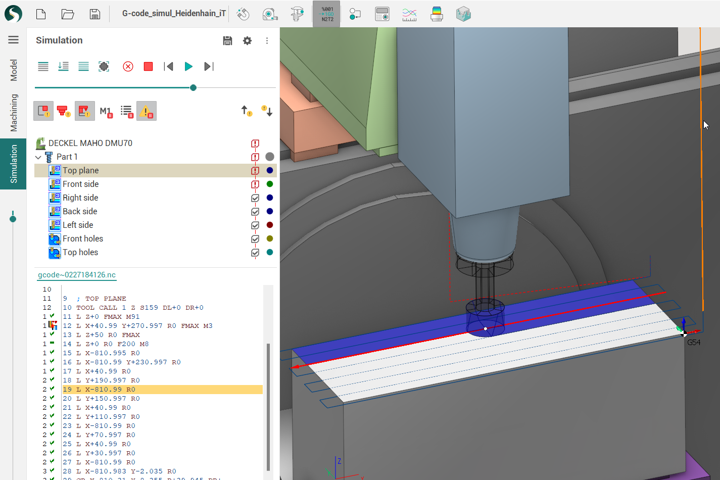
Postprocessing and G-code simulation
.NET postprocessors for G-code simulation
.NET based .dll postprocessors now can be used for simulation based on G-code on a par with .sppx postprocessors.
Upgrade to .NET 6.0 version
Now you can use more recent 6.0 version of .NET to create your G-code interpreters and postprocessors.
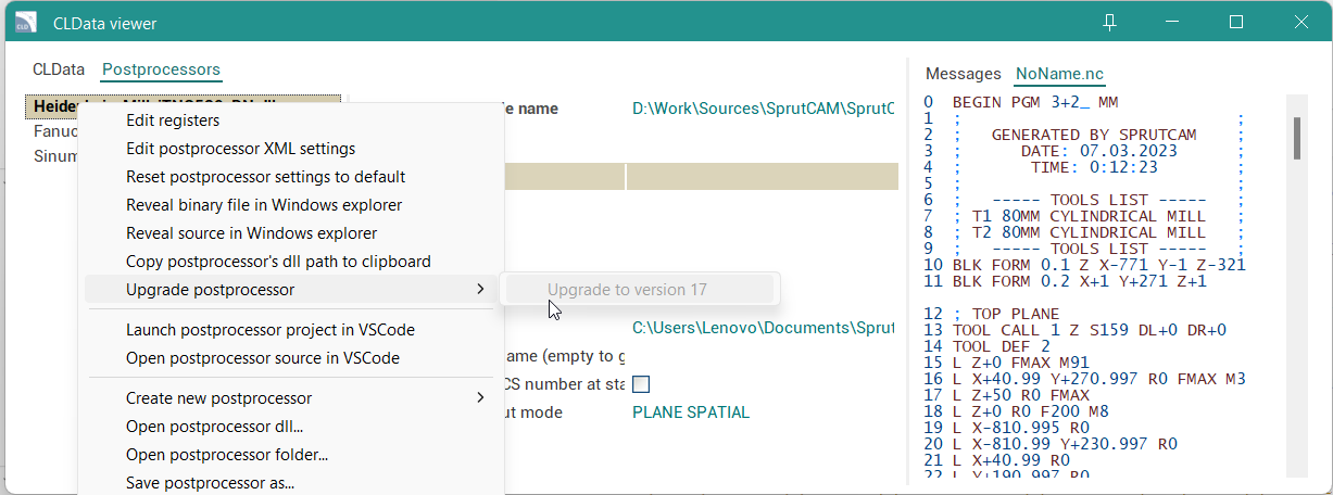
Due to the change in the folder structure in the SprutCAM X installation directory, minor changes in the postprocessor source files may be required in order to compile them in the 17th version. For this reason there is an Upgrade postprocessor context menu item in the CLData Viewer to be possible to automatically upgrade the source codes of postprocessors.
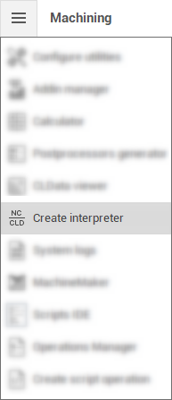
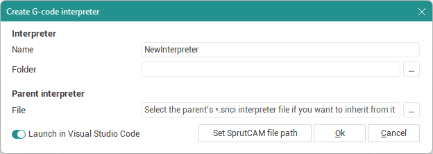
Tool for creating new interpreters
A new tool included to the official distribution to help you create your own .NET based (C#) G-code interpreters.
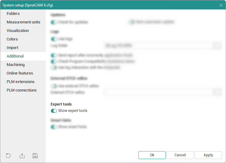
It is located in the utilities menu and is displayed when the Show Expert Tools option is enabled in the system settings.
MachineMaker improvements
There are a lot of improvements in MachineMaker:
Support of optional machine equipment for Milling machines
Support of machine equipment in Robot Cells
Machine validation
Mill machine templates
Geometry measuring
Smart input fields
Undo transformations
Multiaxis machines support
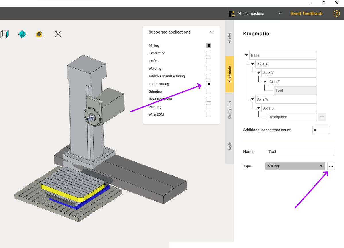
It is possible to define tool type, so you can create Lathe machines now
Interactive 3D model simplifier
CAD enhancements
Design module enhancements
Visual overhaul and better user experience
The user interface has undergone a complete makeover. New icons, ui components and gizmos make for a whole new look and feel.
Support of High DPI screens. Everything looks and works great on all display sizes and screen resolutions.
The new function bar provides at a glance access to the complete CAD functionality.

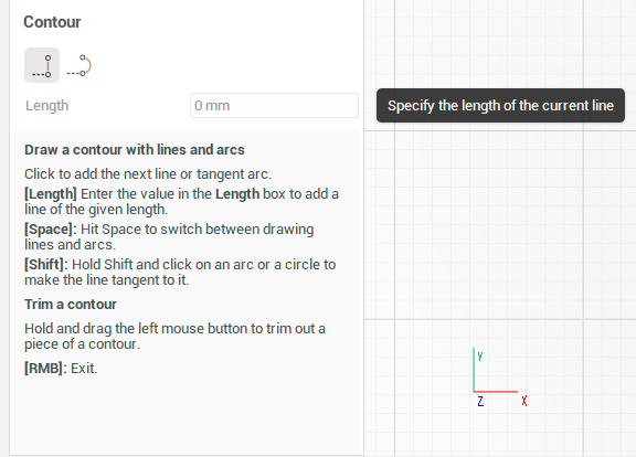
Tooltips and user promts. Hover the mouse over a parameter, if you don't know what it's doing. When sketching or creating a modeling operation, a user prompt with all available options of the mode is displayed in the bottom left corner.
Quick access to design examples. Quickly become familiar with the CAD functionality by discovering the provided design examples.
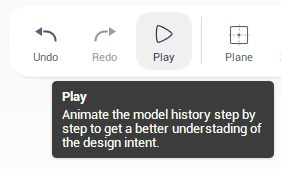
Play mode. Animate the model history step by step to get familiar with the design intent.
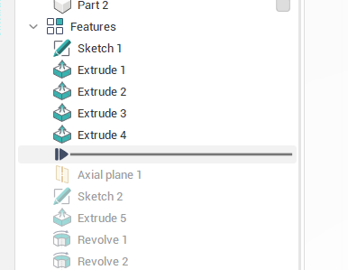
Full-fledged work with the model history
Drag the Rollback bar with the mouse to get back in time in the model history and make drasting changes to the model not possible otherwise. Quickly move the rollback bar across the tree simply by double clicking on a modeling operation in the model tree.
Reorder modeling operations with drag and drop.
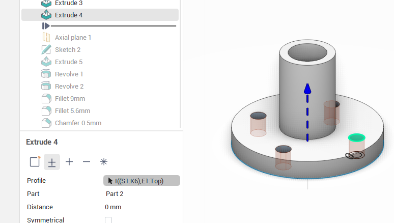
Edit the job assignment of modeling operations. Reassign profiles, faces or edges of operations after they has been created.
New 3d modeling operations
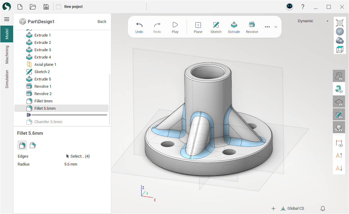
Fillets and Chamfers. Round sharp corners of the model with the given radius and create chamfers.
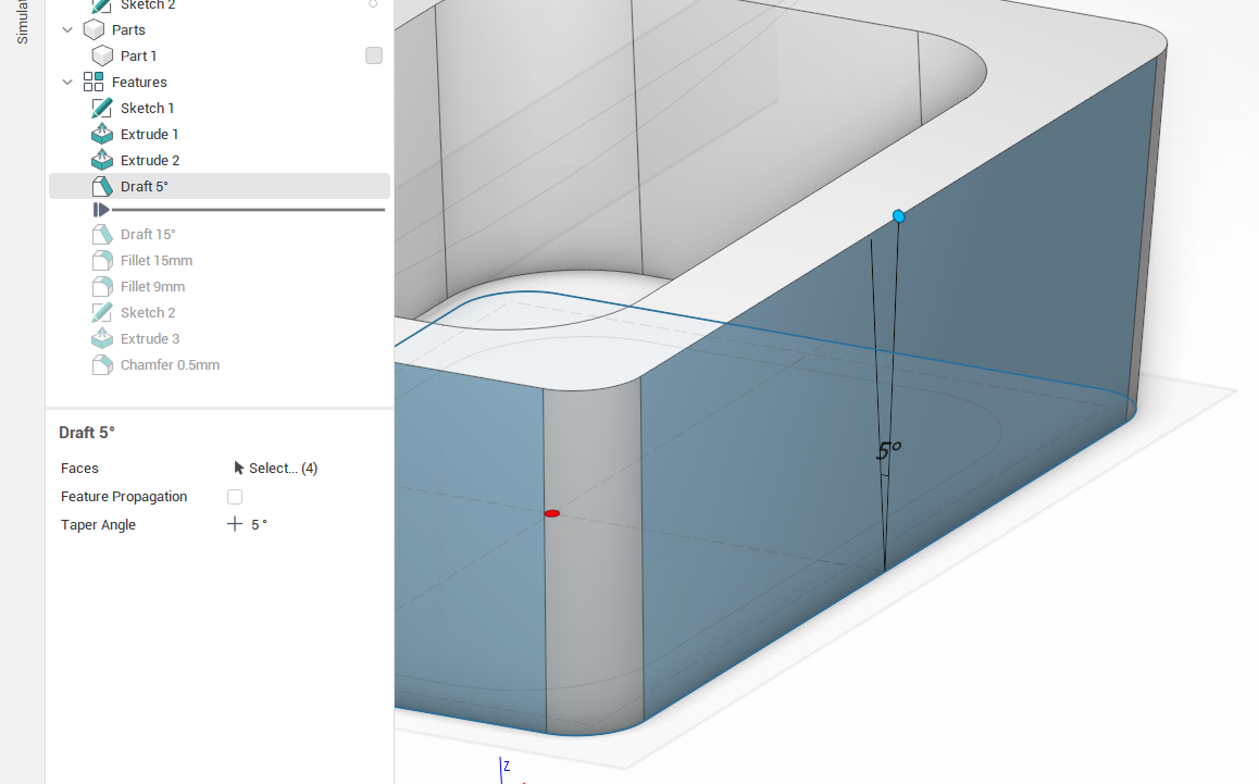
Draft. Incline faces of the model by a given angle relative to a base plane.
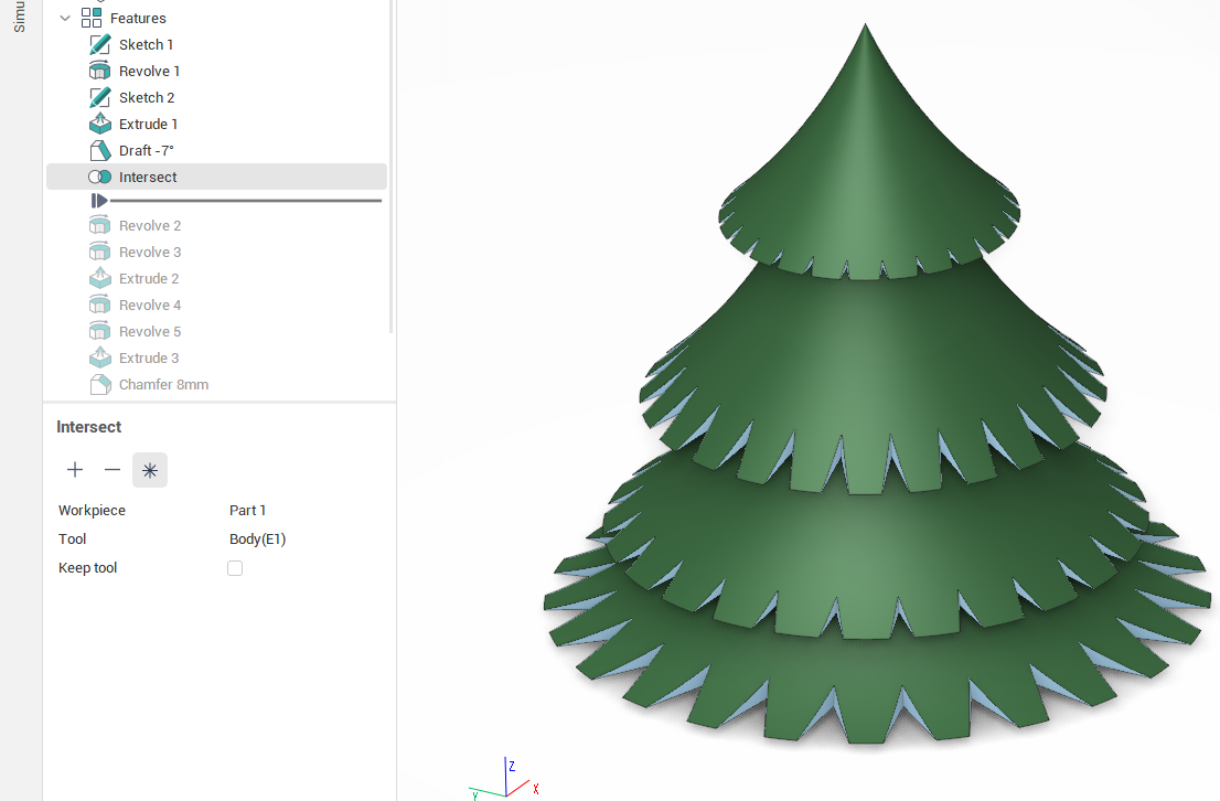
Combine. Combine two parts together with boolean addition, subtraction or intersection
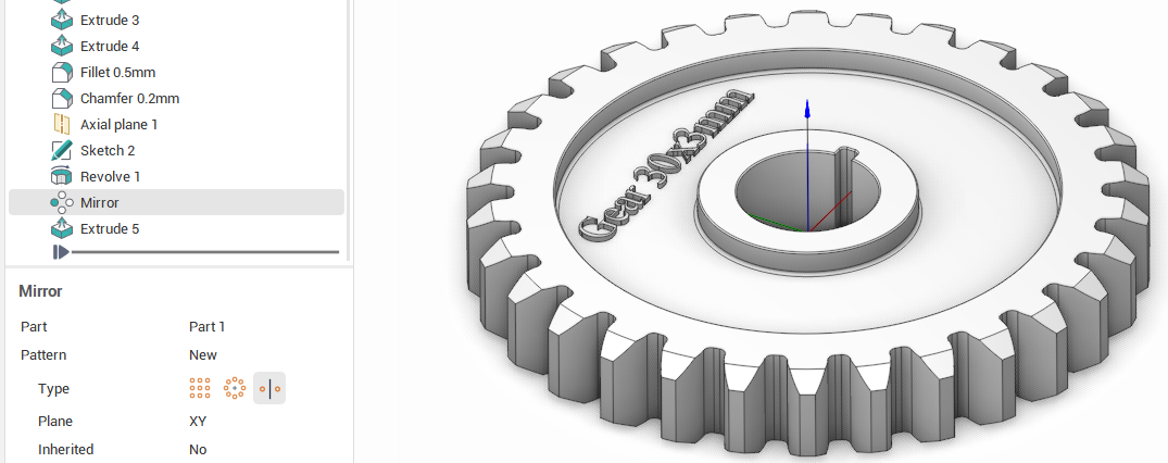
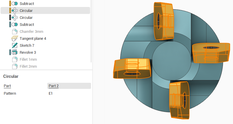
Design symmetrical parts or create patterns of parts with Pattern.
New sketching tools
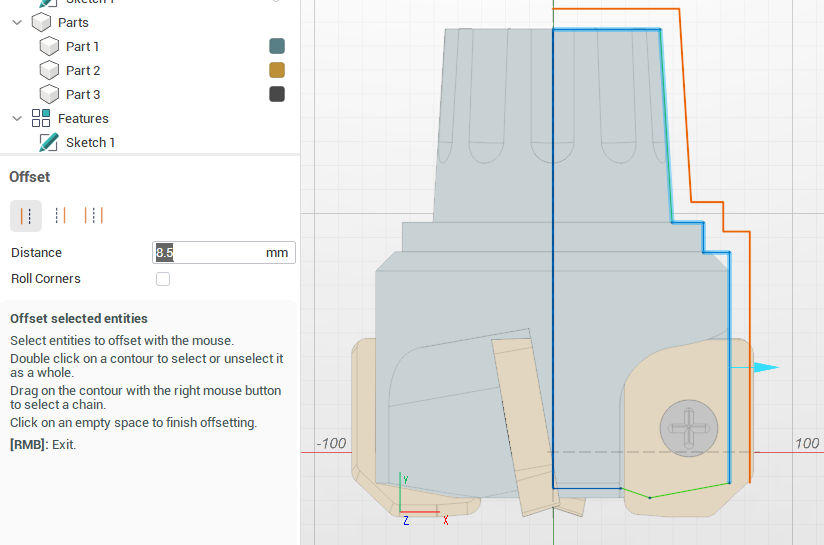
Offset. Contour offsetting is now available as a separate sketching tool with more advanced options and automatic fish tail removing.
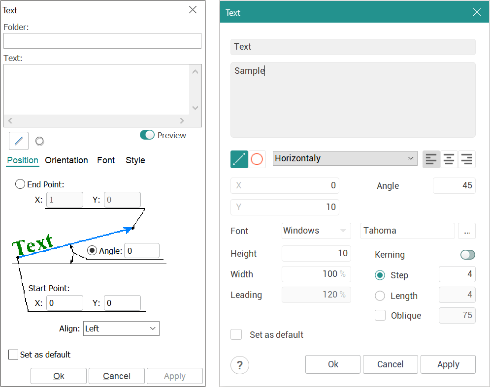
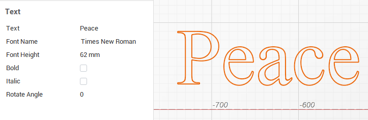
Text. Create contours from text to use them in modeling operations.
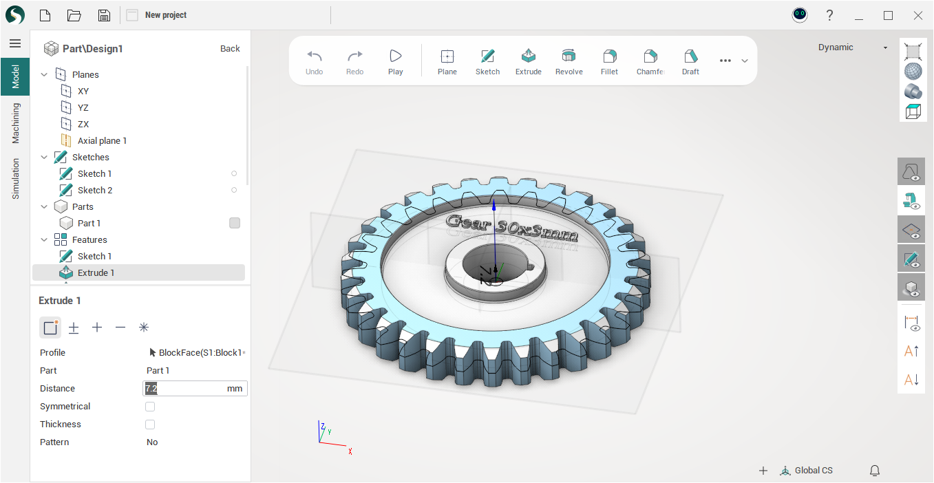
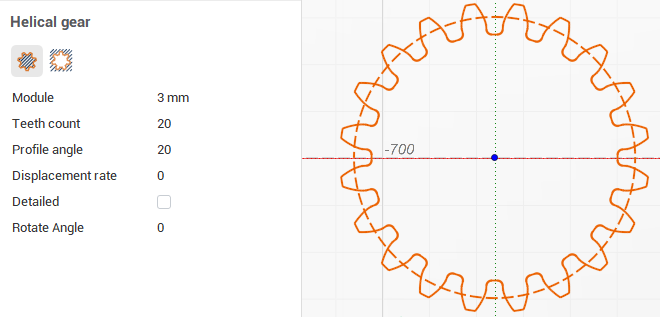
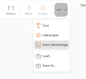
Spur gear. Create spur gear profiles with parameters.
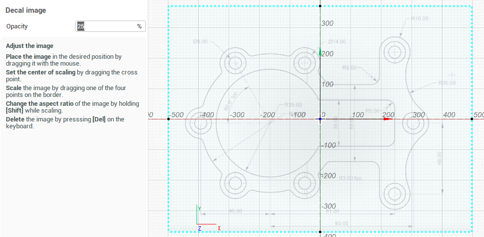
Decal image. Based on user feedback, the decal image insertion is now more easily available through the function bar.
Better stability and performance
Many stability issues and small bugs has been fixed. Model regeneration times have been significantly reduces in many scenarious.
New CAD import capabilities
New CADs Addons:
|
Internal Importer |
Version |
|
2021 SP5 |
|
|
SolidWorks |
Up to 2023 SP0 |
Minor changes
Main application executable file changed
The main executable file of the application has been changed. Now it is sc.exe instead of SprutCAM.exe. This is not just a file name change, the application type has changed. Now the start file is a .NET application. This opens up new opportunities for SprutCAM X extension developers. It becomes possible to write your own plugins and operations for SprutCAM X using the freely available C# language and development tools such as Visual Studio Code.
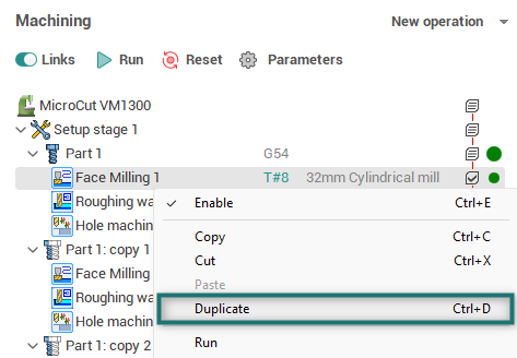
New item 'Duplicate' in the context menu of the list of technological operations
A new menu item - "Duplicate" has been added to the context menu of the list of technological operations (in the <Technology> working mode), which allows you to copy and paste the selected operation with one click.
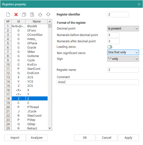
Post Processor generator
New Trailing zeros output option in Registers
In addition to the previously existing Yes/No options, a new one is: add .0 to integers.
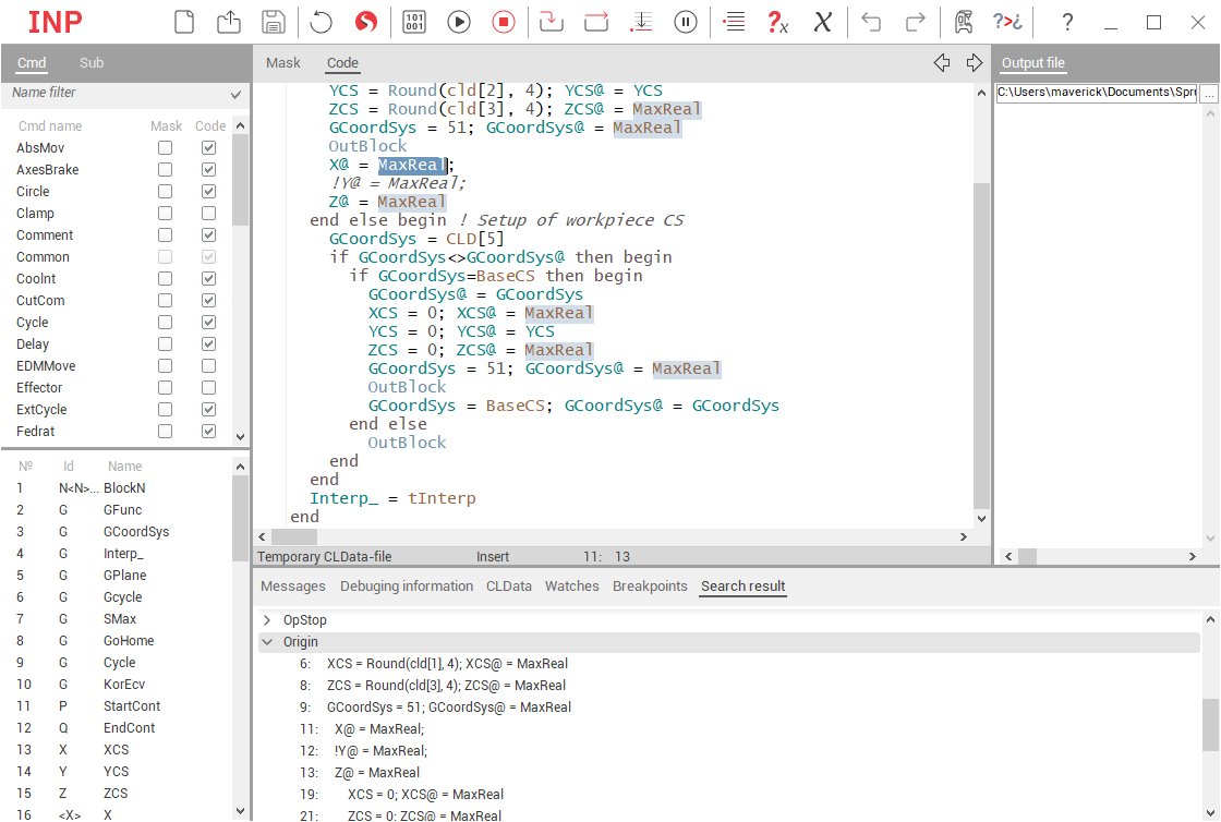
Search in all commands and subprograms
After double-clicking on a word in the editor, an additional tab with search results will open with the ability to navigate through these results.
2D arrays and records
Read more about two-dimensional arrays and records, their declaration and using in documentation.
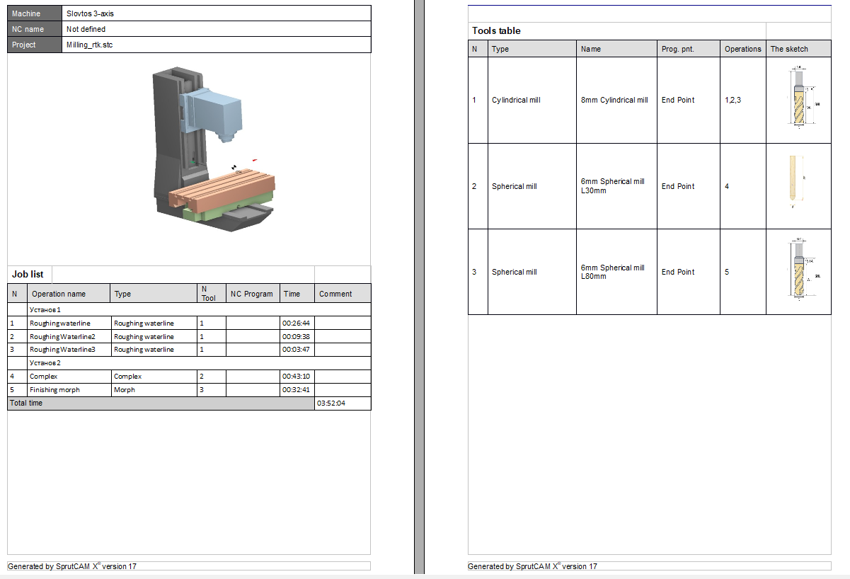
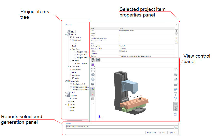
Report generation
Report generation window was changed.
Now it contain 4 parts:
Project tree nodes at the left part of window;
Parameters panel at the right top part;
Graphical window at right bottom part;
Report selection panel at the bottom part.
New features
Selection items output in report;
Creation customer parameters for each project tree node;
Tuning images for each project tree node;
Helper for pattern creation commands;
Output operations by setups.
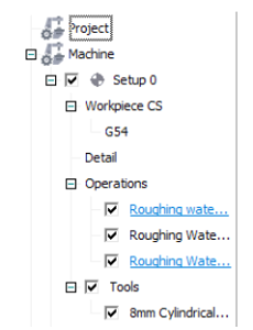
Selection items for output in the report
The main nodes of the project tree can be select for output in the project by checkboxes.
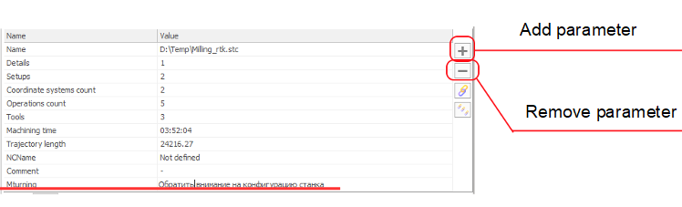
Adding customer parameters for each project tree node
For each node it is possible add a custom parameters and output they in the result report.
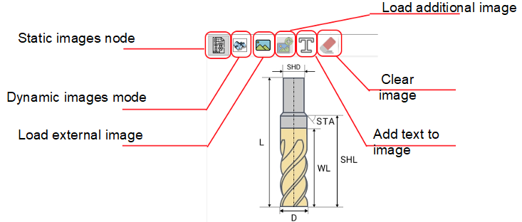
Tuning images for the each project tree node
Images can be defined:
1) Dynamically with the graphic window;
2) By the static image or screenshot of graphic window;
3) By the external image.
On the static images can be added a additional images and text.
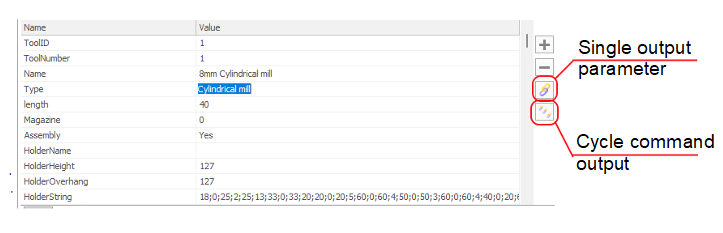
Helper for pattern creation commands
For creation the parameter output command it is enough to select the parameter in the list and press the correspond button.
Output operations by setups
Example of report.