3D curve milling
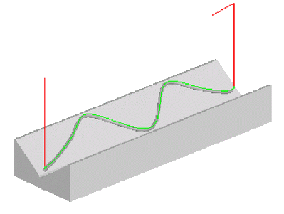
This operation is designed for performing machining along any spatial curves.
The model being machined is either an imported model or created using 2D geometry. Every profile in the list can have its own machining method: either the tool center passes along the contour or, the left or right edge touches the contour. If the tool is offset (left or right) then it is possible to define an additional stock, a positive stock value is added to the machining side. If the tool follows the center of the contour then the stock value will be ignored. The Z coordinate for every point of the toolpath will be calculated according to the Z coordinate value of the corresponding curve and the defined offset value.
When machining a curve from left or right and complying with the condition that the tool contour touches one section, the mill contour theoretically may cross over the curve to another section. These areas correspond to equidistant loops of a horizontal projection of the curve. That means that, when machining such areas one may get a gouge in the model. In order to avoid this, the described faulty toolpath sections are automatically detected and deleted.
If in the operation there is a defined workpiece and/or restricted areas, then only those curves that lie within the workpiece and outside the restricted areas will be machined. If no workpiece or restrictions are defined then all selected curves will be machined.
Machining is performed in a series of 3D passes of the tool. The passes are created offset in Z from each other based on the Z step value. The number of passes and their Z displacement value depends on the machining levels and the step value entered on the parameters page.
In the same window the user may define the machining tolerance and the stock. For curves that are machined from the left or right, any stock amount is added in the offset direction of the tool, and when machining along the tool center – it is ignored.
If the operation is performed using a local coordinate system or if using a rotary head then the toolpath will be created according to how the milling cutter touches the curve (left/right/center). The tool will be parallel to the Z-axis of the local coordinate system of the operation. This corresponds to the construction of equidistant curves in the XY plane of the local coordinate system that are equal to the tool radius plus stock, and the Z value is equal to the Z coordinate of the corresponding point on the source curve in the local coordinate system.
The initial machining point for an open curve corresponds to its first or last point (depending on the selections on the Model page for side of machining and <Inverse> and also the status of <Allow reverse direction> option). For closed curves, if an initial point has not been defined on the Model page, the first machining point will be selected automatically, for the minimization of tool movements.
When joining passes into the resulting toolpath, the defined approach method will be added to the beginning, and the retract method at the end. The joining order depends on the combination of the settings: <curve/offset>, <compensation>, <with return>.
When setting the machining order <By Contours>, each contour will be machined to full depth before moving to another contour. When setting <By Depth> each contour will be machined at the current cutting depth, the tool will move to the next depth only after all contours are machined.
Selecting <Idling Minimization> optimizes the order that contours are machined in. When deselected the contours are machined in the order that they appear on the model page.
If <Allow reverse direction> is selected, then the cutting order will be set with regard to the <Idling Minimization> setting. The side of contour machining will not change. Otherwise the contours are machined in the order that they appear on the model page.
Note: If you need to dictate the order of contour machining and the direction of their machining, then it is recommended to turn off the Idling Minimization mode and restrict the use of reverse direction. This will ensure that the order and the direction of machining will correspond to the order defined on the Model page.
See also:
Operations for the 3-axes milling