5 axes positioning
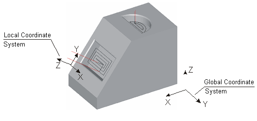
5-axis positioning provides a convenient method of manufacturing parts that require milling on multiple faces by minimizing setups. The figure below shows an example of a part that requires milling from 2 different orientations. With 5-axis positioning, this entire part can be milled with a single program.
5-axis positioning is performed by setting the appropriate values to the <Rotary Axes> parameter section in the operation Setup panel. All the milling operations may be used for part's processing from different sides. In the case the equipment doesn't allow to rotate the part or the axis of the tool, it is necessary to change the scheme of part's workholding.
For a particular operation you can set the actual values for the rotary axes position as you need. After generating toolpath the Approach section of the CLData will contain the commands of rotary axes positioning. The entire program is then generated with regard to the new rotary axes position.
In SprutCAM X you can easily set the rotary axes position by clicking on the part face which the tool axis has to be aligned to. This method is performed with the following steps:
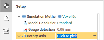
In the operation Setup panel select the <Rotary axis> parameter and press the ellipses
 button at the right of the caption. The <Align Tool> dialog will appear:
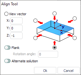
In the dialog you can see and edit the orientation of the current tool axis in the Global coordinate system.
To align the tool with regard to a flat or a cylindrical surface just click on that surface in the graphic view. The 3d Model visibility button should be turned on.
Press <Ok> to apply the changes or press <Cancel> to discard the changes and close the window.
By default an operation generates the toolpath in the Workpiece coordinate system (G54 - G59), but you can change this behavior by specifying the Operation local coordinate system parameter in the Setup panel.
Many today controls require definition of the local coordinate system for 5 axis positioning. Without this definition the position of the workpiece zero point (G54) and the position of the tooling point is not updated after changing the position of rotary axes - the control behaves as it knows nothing about the machine kinematics - as a regular 3 axis control. But when you specify the local coordinate system (the PLANE function at HDH, the ROT function at Sinumeric), the control updates the position of the workpiece zero and the position of the tool tip regarding to the actual workpiece-tool orientation. It looks like at the following figures.
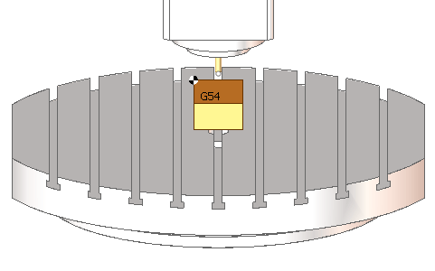
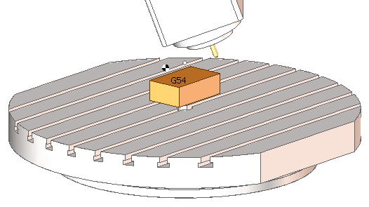
Initial machine configuration (A0 C0). G54 is at the top left corner of the workpiece, the tooling point is at the tool tip
Machine configuration after 5 axis positioning without Local CS enabled (A20 C-40). The workpiece and the tool are moved, but the G54 and the tooling point still stay the same. The generated toolpath will be depend on the workpiece setup and the tool length
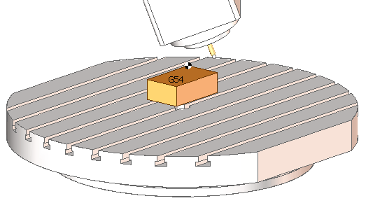
Machine configuration after 5 axis positioning with Local CS set to AUTO (A20 C-40). The G54 is again at the workpiece top left corner, the tooling point is again at the tool tip. The generated toolpath will be independent on the workpiece setup / tool length
So generally you should use the <Auto> option of the Local CS parameter. For more information refer to the Operation local coordinate system topic.
See also:
Workpiece coordinate system (G54 - G59)
Operation local coordinate system Mill-turn Machining