Operation local coordinate system
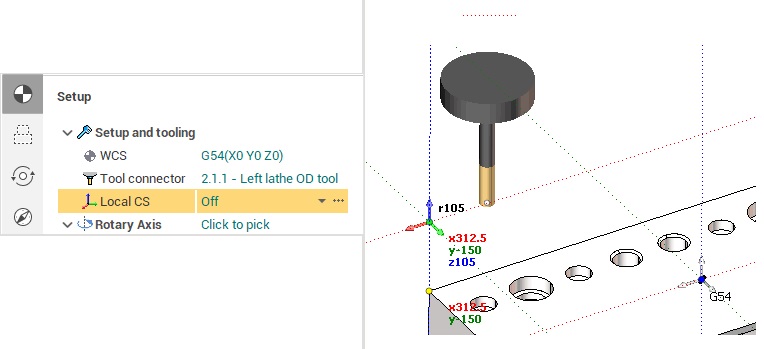
An operation generates the toolpath in a local coordinate system. You can see the local coordinate system of an operation in the graphic view while working in the Technology and the Simulation modes. It looks like at the picture below.

By default an operation generates the toolpath in the workpiece coordinate system (G54). However you can change this behavior by specifying the Local CS parameter in the Setup panel.
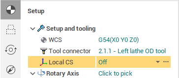
The parameter can be set by two ways. You can select the local coordinate system from the drop down list, and you can set the local coordinate system in the interactive mode by clicking on the ellipses button.
The drop down list contains the following options:
1. <Off> - the local coordinate system is disabled - the toolpath is generated in the workpiece coordinate system.
2. <Auto> - the position of the local coordinate system is determined by the current position of the machine rotary axes. The Z axes of the LCS is aligned to the tool axis direction. The origin of the LCS coincides with the position of the workpiece zero point (G54), but you can easily relocate it in the interactive mode (the ellipses button).
3. The list of geometrical coordinate systems. To define the operation local coordinate system exactly the same as you want you can create an appropriate geometrical coordinate system and select it from the Local CS drop down list.
By clicking on the ellipses button next to the Local CS parameter you enter the interactive mode of Local CS definition. In this mode you can change the position of the Local CS origin in the graphic view using the standard drag&drop technique. Just hover the mouse pointer over the local CS on the screen. It should become highlighted. Than click on it with the left button to start dragging. After that you can change the location of the coordinate system by snapping either to the part or to the workpiece geometry.
After positioning the local coordinate system just click OK to apply the changes.
When you enable a local coordinate system SprutCAM X generates the Origin command in the header section of the CLData. The origin command contains all the data required for postprocessing toolpath. These are:
1. MCS - the position of the local coordinate system relative to the machine coordinate system (G54). This matrix is used in old controls without the tool center point management function (TCPM).
2. WCS - the position of the local coordinate system relative to the workpiece coordinate system (G54 rotated together with the workpiece). This matrix is used in the controls with the TCPM function.
3. Coordinates of the rotary axes positioning the tool axis along the z axis of the local coordinate system.
In addition some controls do not support the definition of a local coordinate system by spatial angles. Those controls require the local CS is defined by the actual machine rotary angles, aligning the tool axis direction along the Z axis of the local coordinate system. SprutCAM X supports such controls. The corresponding option is available under the Control parameters section in the machine properties.
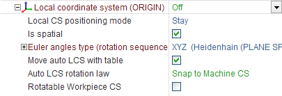
Another control feature is the Local CS positioning mode. This option determines the behavior of the control when it treats the Origin command. SprutCAM X supports the following modes of the Local CS positioning.
1. Stay - the origin command does not move the machine axes.
2. Turn - the origin command rotates the machine axes in such a way the tool axis direction becomes aligned with the Z axis of the local coordinate system.
3. Move - the origin command rotates the machine axes to align the tool axis with the Z axis of the local coordinate system and moves the linear axes in such a way the tool tip position stays the same relative to the workpiece.
In the next table there are commands for the most commonly used CNC controls which can be generated by the postprocessor instead of the <ORIGIN> command.
|
Origin |
G92 G68 |
TRANS ROT |
Cycle 7 Cycle 19 |
See also:
Geometrical coordinate systems
Machine coordinate system G54 - G59