Defining part, workpiece and fixtures
Selecting a part, a workpiece or fixtures in the machining tree forces the bottom part of the window to take the following look.
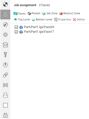
Each item of the list defines a surface, a solid etc to take into account while calculating toolpath. The item caption displays the full path to the item in the geometry model tree. If the source object of an item is removed or renamed the item is marked with the question sign. The icon left to the item defines either the item type or the way the item was achieved from the source object. To add an item of some type to the list the appropriate buttons are used.
The  button adds selected faces to the list. If no faces are selected then the dialog with the geometry model tree appears. In this dialog one should find and select the faces, the meshes and the groups to be added to the list. If a group is added then only 3D-objects of the group will be taken into account.
When defining a workpiece the <Add Faces> button is used to make a <solid> from the selected faces. The solid item represents a bounded space. It is marked with the  icon. There are two possible ways to make a solid:
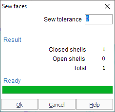
By sewing faces. The added faces need to form one or more solids. The tolerance that the faces are connected with to each other is specified in the dialog that appears.
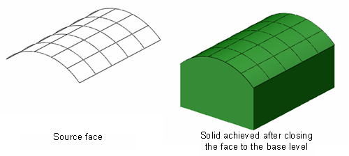
By closing faces to the given Z level.
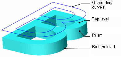
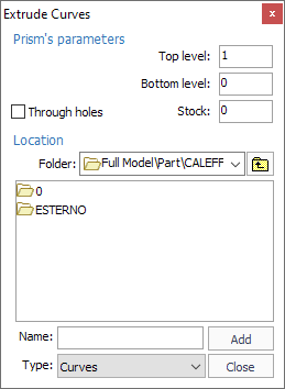
The  button is used to make a prism. Closed curves as well as group of curves forming closed profiles can be used as the source objects. The specified curves are used as the base of the prism. In addition, the top and the bottom levels of the prism should be specified.
If one wants define a prism with holes and isles he needs place the source curves in one folder and specify that folder as the prism base. As a rule the outer curve defines the body and the inner curves define the holes. It is possible to set the outer curve as a hole for the fixtures. To do it is necessary to check the <Throw hole> box.
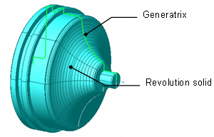
The  button makes a revolution solid generated from the specified curves. If no curve is selected the dialog that helps find and select the generating curves for the solid appears.
The special link items are introduced. Those are used to provide relations between operations as well as to define simple parametric features. At that, a link item is the reference to the source object, that in turn can be a reference to another object. Changing a source object forces all link items to be reset and/or recalculated. To add a link item to the list one should press the  button. The result depends on the parameter type being edited. If the part is defined then the reference to the part of the previous operation will be added. If the fixtures are edited then the reference to the fixtures of the previous operation will be added. If the workpiece is modified then the dialog will appear that offers the following items to be added.
 – the workpiece of the previous operation.
 – the machining result of the previous operation.
 – the box around part.
 – the cylinder around part.
See also: