Waterline roughing operation
The waterline roughing operation is used for preliminary rough machining of models of a complex shape, which have significant differences to the workpiece.
A model being machined by the waterline roughing operation is assigned by a set of solid bodies, surfaces and mesh objects. For every geometrical object or a group of objects, an additional stock, which during machining will be added to the main stock of the operation, can be defined.
The workpiece can be assigned as a cube, cylinder, a mould with stock or prismatic form, as residual material after machining by previous operations, and also as a free-form geometrical model, consisting of solid bodies, surfaces, meshes and prisms whose bases are projections of closed curves. In the restricting model, solid bodies, surfaces and meshes which are required to be controlled during machining, and also machining areas and restricted areas, defined by projections of closed curves can be defined.
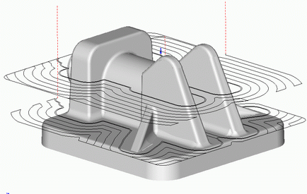
The operation performs removal of the entire material of the workpiece, which lies outside of the model being machined and outside the restricting model. The material is removed using horizontal passes of the tool layer by layer. The step (or depth of the layer being removed) can be fixed or calculated according to the defined height of the scallop. Either depending on the selected strategy, the material for every layer can be removed using spiral passes, directed towards or out from the center, and by using parallel passes.
Transition to the next machining depth can be achieved either by using one of the plunge methods (axial, by spiral, zigzag), or through drill points. If the latter method is used, a search is made for a hole of an appropriate depth/diameter. The search will first be made in the list of holes for the operation, and then in the open list of holes for the machining process. If no appropriate hole can been found, then the system will select appropriate coordinates for it automatically, at an optimal position. The coordinates for the center of the new hole, if possible, are rounded. If when the operation was created, the hole machining operation was chosen as its prototype, then the list of holes will be copied into the operation and used when searching for appropriate hole for tool plunging.
When using a local coordinate system or a rotary head, the position of the model being machined will not change, the tool rotation axis is parallel to the Z axis of the local coordinate system, and all work passes are located in planes that are perpendicular to the horizontal plane of the local coordinate system.
There is can to be used quick calculation method also.
For roughing waterline operation Adaptive feedrate feature available.
See also:
Operations for the 3-axes milling