Toolpath multiplying
The Multiply toolpath features of the SprutCAM X can help with machining of repeating model fragments. You can define machining for only one of repeating parts and then just determine the amount and orientation of the same elements.
There are 2 different ways to perform it: multiply toolpath by axis and multiply scheme.
The <Multiply toolpath by axis> feature more suitable for lathe-mill machines. It can multiply toolpath only by one machine axis (frequently it is the rotary axis, for example C-axis of lathe milling machine, when coordinate system does not rotate with the workpiece together when changing axis value). This kind of transformation is possible if source set of toolpath commands may be converted correctly with only one axis value replacing. So you need to define in parameters the name of the axis to convert, the step to increment value of this axis and the count of repeats. Frequently source portion of NC code that used for transformation does not contain the value of axis you want to use for multiplying. For example when we have indexed rotary machining, C rotary axis presented only inside approach part of the toolpath to provide desired tool-workpiece orientation but the main part of machining toolpath is fixed in a space and contains X, Y, Z movements only. So this unchanged part of toolpath can be formalized as a subroutine inside NC-code and can be called so many times as you need with changing only C axis orientation before each call. To make such transformation it is enough to enable Formalize as subroutine parameter and input desired subroutine ID (name or number).
We can have more complicated case of transformation when many coordinates of source toolpath must be changed at the same time (for example X,Y and Z) almost inside each NC block to repeat machining at the neighbor place. For 5-axis machines with TCPM (when coordinate system rotates with the workpiece together) only this kind of transformation is possible. In this case you need to use Multiply scheme transformation instead. This transformations works another way. It converts not ready toolpath commands, but it transforms source geometrical curve of toolpath in space and only then converts it to the toolpath commands.
Multiply scheme provide different spatial strategies of transformation:
Two dimensional array;
Two dimensional array (manually);
Round array;
Round array (most distant);
Round array ( manually );
Level array;
Axis symmetry
Instance count, steps, center point and sometimes angle must be determined depend on selected strategy.
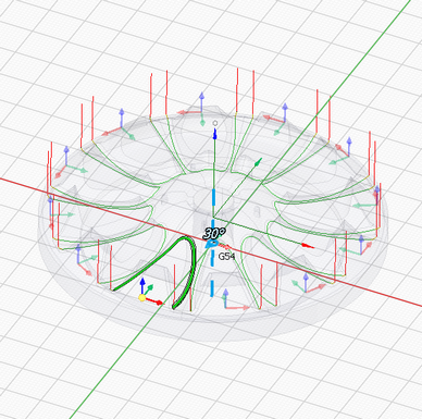
When selecting Multiply scheme parameter of the operation inside inspector then its graphical visualization appears on the screen. You can directly see an amount of transformed items and their orientation. You also can drag some hotspots (for example center point) with mouse button and input multiplying step values.
Base coordinate system defines the coordinate system with respect to which the transformation will be performed. It can be: Tool CS, Workpiece CS, Global CS or any other geometrical CS you have created before. Also additional translation and rotation of this CS can be defined inside Additional transformation group of parameters.
Use feature CS parameter allows to perform machining of each multiplied item with their own local CS. Before calling the each next item's machining the ORIGIN command will be added that will be converted by the postprocessor to PLANE SPATIAL, CYCLE800, G68.2 etc. transformation command depending on used type of controller.