Workpiece coordinate system (G54 - G59)
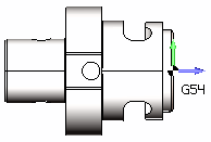
<Workpiece coordinate system (G54 – G59)> defines the NC-program "zero" on the workpiece. You can always see the Workpiece CS on the screen while working in the Technology and the Simulation modes. It looks like at the following picture:
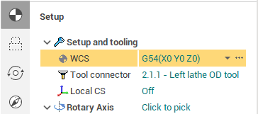
The workpiece coordinate system is specified under the <Workpiece CS> parameter in the Setup panel.
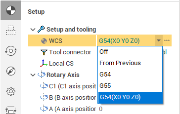
There are two ways you can define the Workpiece CS. You can select the Workpiece CS from the drop down list and you can set the Workpiece CS in the interactive mode by clicking on the ellipses button.
The drop down list contains the following options.
1. <Off> - the workpiece coordinate system is disabled. It means the workpiece zero coincides with the machine zero point G53.
2. <From the previous operation> - the workpiece coordinate system is taken from the previous operation.
3. The list of geometrical coordinate systems of the project. You can use a geometrical coordinate system as the workpiece coordinate system. In this case only the origin of the geometrical coordinate system is used, the axes orientation of a geometrical coordinate system play no role for the Workpiece CS definition.
You can specify the Workpiece CS ID in the interactive mode by clicking on the ellipses button next to the Workpiece CS parameter.
In the interactive mode you can change the position of the Workpiece CS origin in the graphic view using the standard drag&drop technique. Just hover the mouse pointer over the Workpiece CS on the screen. It should become highlighted. Than click on it with the left button to start dragging. After that you can change the location of the coordinate system by snapping either to the part or to the workpiece geometry.
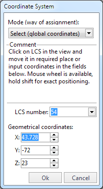
In the interactive mode you can also change the LCS number (54-59 etc.).
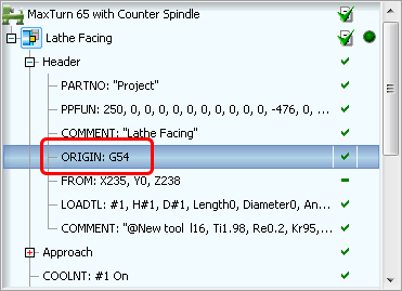
Note that CAM modifies operation header CLData according to your changes. The <ORIGIN G54> command is added to the header in the example:
See also:
Geometrical coordinate systems
Operation local coordinate system