Engraving operation
This operation is designed for the engraving of drawings and inscriptions on flat areas, and also for performing a finish pass along the side walls of pockets and contours using 2 / 2.5D machining.
The model being machined is formed from 2D curves in the horizontal (XY) plane. The model is created by the addition of curves or groups of curves into the resulting model. Any curve can define a scallop, groove or inverse (reversed) curve of a defined thickness, besides this, closed curves can be added as ledges, hollows or inverse areas. Additional stock, which will be added to the operation stock, can be assigned separately for every curve or a group of curves. Machining is performed along the outer contour of the created model with regard to the defined side angle (i.e. the edge of the model is not always vertical).
Only those areas, which lie within the workpiece or outside of restricted areas, will be added to the resulting toolpath. The workpiece, machining areas and restricted areas are defined by projections of closed curves. If the workpiece or restricted areas are not defined, then machining of the entire model will be performed.
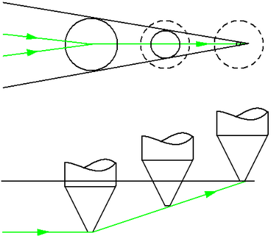
Horizontal passes of the tool are used to form the main edge of the model using the defined step between passes. In order to form sharp inner corners and for machining of smaller width areas it is advised to use the 3D clearance option. This means that when working with a profiling tool, the diameter of which decreases towards the end point, machining of more "narrow" areas with simultaneous increasing Z value is possible.
If the operation is performed in the local coordinate system or if using a swivel head, then the model being machined is formed from curve projections onto the horizontal plane of the local coordinate system, the main work passes are parallel to the same plane, and during 3D area clearance the tool will be raised to the appropriate value along the Z axis of the local coordinate system of the operation.
The joining order of separate passes depends on the defined machining direction (upwards or downwards). Step-over between passes can be performed along a contour, with generation of intermediate approaches/retractions or via the safe plane.
See also:
Operation for 2/2.5-axes milling
4-axis milling with using of the engraving and pocketing operations
Using design features in an Engraving/Pocketing operation
Job assignment for engraving and pocketing operations