Work modes
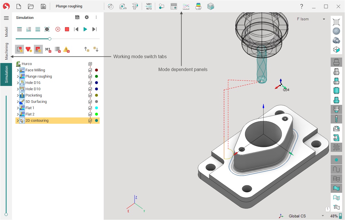
For convenience, the system interface is divided into several working modes. Tabs are used to switch modes in the main window. When you change the tab, the contents of the panels in the main window change:
Working mode content page in the left part of the window.
Working mode toolbar in the middle of the uppermost window pane.
Due to this, the number of buttons displayed simultaneously on the screen is significantly reduced, the interface is simplified, the space for main work expands.
The sequence of tabs approximates the order of basic user actions when working on a project, although the relationship is not strict.
The following briefly describes the purpose and appearance of the window for each of the modes.
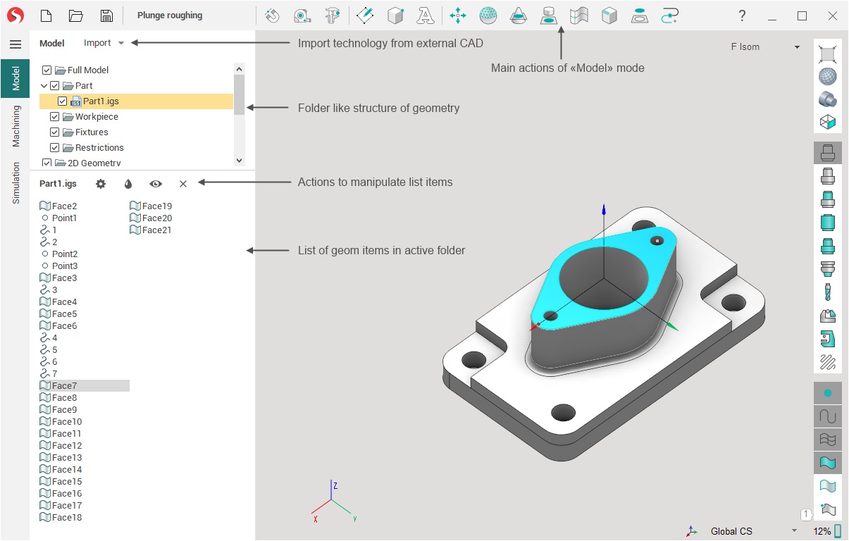
Model
In the Model mode the user can: import geometrical data (CAD) files, modify (cut, delete etc.) the structure of a geometrical model, spatially transform (move, rotate etc.) objects, generate new elements (copy, draw, intersect, triangulate, etc.) from the existing ones, and manage the object's visual properties.
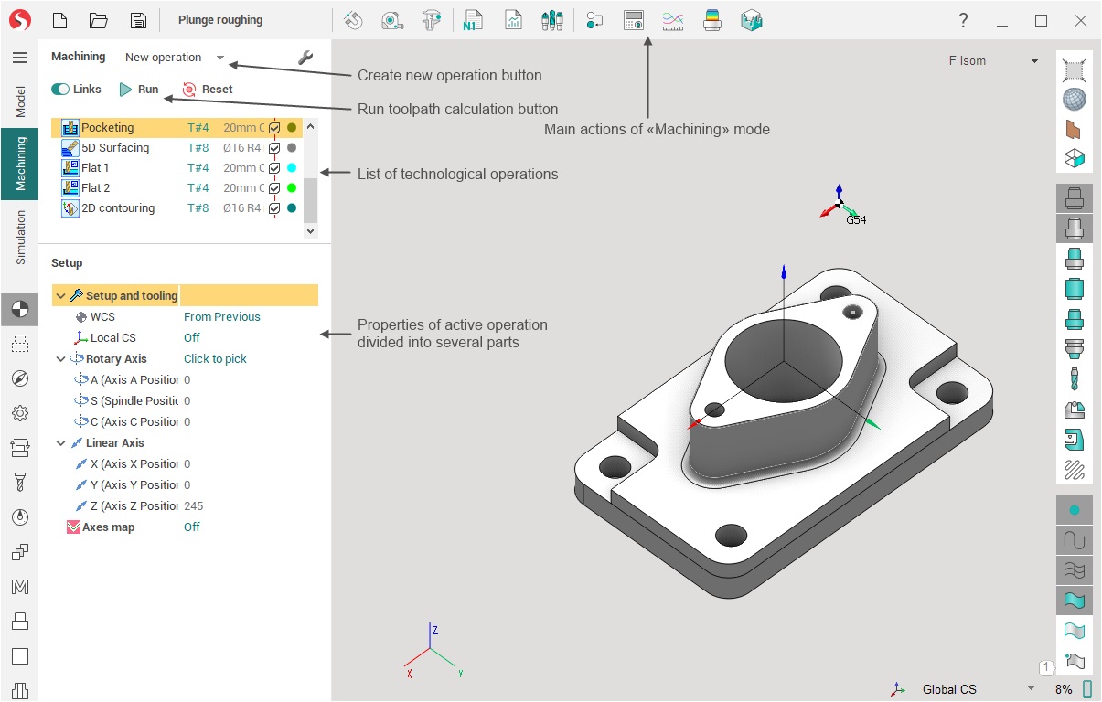
Machining
In the Machining mode the user creates the machining process of the part, choosing from the list of available technological operations. The operation determines the processing strategy and the type of toolpath. Here also, the fine-tuning of all the machining operations parameters and the calculation of the tool movement toolpath can be performed. After receiving the toolpath it can be seen on the screen, as well as the preliminary result of machining. After debugging the process, you can run the postprocessor to generate the NC program and machining report.
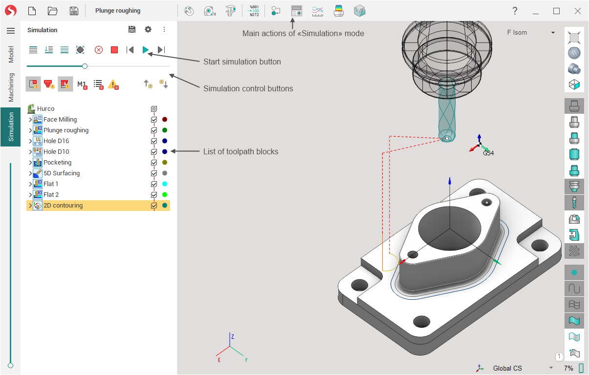
Simulation
In the Simulation mode user has access to integrated machining simulation tools that allow the user to control dynamically material removal, machine collisions, visualization parameters and check the generated toolpath by blocks.
There are several buttons that are common to the Machining and Simulation modes.
 Machine control panel allows you to watch and modify the current values for all machine / robot coordinates.
 The Graph of the axes displays the change in each of the machine axes over time in the process of working out the toolpath of the current operation as a graph. This allows, for example, to find unfavorable for the machine parts of the toolpath with bounce, which can lead to vibrations.
 allows you to display the difference between the original part and the result of machining in the form of a color scheme where each color is associated with a specific deviation range between the compared elements.
 panel allows to view zones of the part where tool holder does not have collisions and to determine the best angle for parts processing.
See also: