Generating tools list
SprutCAM X generates the tools list. This document contains the information for the machinist to machine the part. The tools list can be edited by the text editor and printed. The document is saved in the ODT format. The way to generate the tools list is defined in the setup window.
The tools list document has the next structure:
The drafts of the tool path the and model with the dimensions to set up the workpiece;
The operations list. Every operation has the own machining time and the total time is printed. The enabled and calculated operations only appear in the tools list;
The table of the used tools;
The table of the holes coordinates for the pre-drilling for the tool plunge.
Press the  button from the machining bookmark to open the <Tool list> generation window.
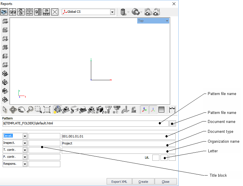
The next panel defines the drafts quantity and disposition:
The draft can contain the workpiece, source model, tool path, origin, axes and dimensions. These objects appear if press the corresponding buttons in panel:

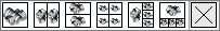
SprutCAM X automatically chooses the view and creates the dimensions. The dimensions can be shown in the top, bottom, left, right, front and back views only. Three distances to the origin and three overall dimensions are shown.
Dimensions example:
Fill the fields and click  to create the tools list. The editor to show the document is defined in the setup window.
If document will be used later it must be saved.
Use  to close the dialog.
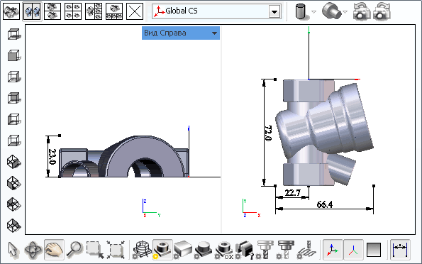
Example of result document show below:
SprutCAM X report generation system has added the ability to generate reports based on templates in the Opendocument format (.odt).
Formation of the template is performed directly in editor supporting the Odt format.
Setting variables for substitution is done only in the notes object. The data source for filling out the template is a stcx file that is automatically generated when the template is generated. It is an XML file that can be opened by any editor or viewer that supports the XML format.
To insert a variable, specify the full path to it in the structure of the stcx file.
The following is an part of the stcx file opened in Internet Explorer:
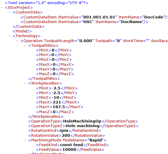
For example, to display the values of an operation type in a report, create a note in the template (Ctrl + Shift + C) with the following contents:
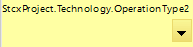
As a result of the command, the value “Hole machining” will be displayed in the report.
Similarly, any other values are output.
Elements can also be accessed by index. For example, a call to a node containing the project name can be written as follows:
StcxProject.CustomData [1]
The entry means that we need to take the second (numbering of elements from 0) child node of the CustomData element.
Such a record can be used only for elements whose order does not change. For example section CustomData, ToolpathBox, WorkpieceBox, etc.
Next, you need to take the value of the ItemValue attribute. To access attributes, use braces {}.
The full entry will look like:
StcxProject.CustomData [1] {ItemValue}
For forming tables, the ForEach command word is used.
The Technology and OpXMLParams child nodes are a list of project activities.
After generating a report on this template, a table will be generated in which rows will be added by the number of operations in the project.
To add arbitrary variables to the report that you want to display, but which are absent in SprutCAM, you can use the following syntax.
VAR (<Variable Name>, <Title>, <Default Value>).
Example:
VAR (Detail, Detail, Case)
When you select a template, a list of available variables is displayed in the RTK window.
A variable can be described in any part of the template. The format of the variable call:
${Variable name}
Example:
$ {Detail}
All commands and variables should be found only in the notes objects.
Separate commands have also been added to work with images.
Images can be added to the template in two ways:
1. By adding a text command
ToolImages - a tool sketch output command.
ToolingImages — a tooling point output command.
FixtureImage — operations fixture output command.
GeometryImage — 3D model output command.
HolderImage — tool holder output command.
JobImage — operation job assignment output command.
MachineResImage — machine state output command.
ModelImage — operation detail output command.
OpToolImage — operation tool output command.
ToolPathImage — operation trajecttory output command.
WorkpieceImage — operation workpiece output command.
All these commands supports index reversal and ForEach command. Image data is generated automatically according to the number of operations in the project.
ProjectImages a command to display images created and saved in a project. Supports index reversal. They can be formed both manually and automatically.
When added in this way, the picture is inserted without formatting and scaling (as is).
1) Using example pictures
In this case, an arbitrary image whose properties and format can be fine-tuned is inserted into the document. When substituting, the image source is replaced, previously configured properties remain unchanged.
The command for displaying the image is set (using OpenOffice as an example) in the Name field on the Settings tab.
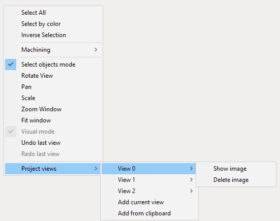
To view images added to the project, call the context menu in the SprutCAM X graphic window and select the Project Views option.
Add current view - Forms the image according to the current view and adds it to the list of project images
Add from clipboard - pastes the image from the clipboard and adds it to the list of project images.
Already added images can be viewed and deleted.
When deleting images, index shift does not occur.
For a better understanding of the principles of working with this type of template, it is recommended that you familiarize yourself with the supplied examples from the SprutCAM X distribution.
See also:
Common principles of technology creation