Waterline finishing operation
The waterline finishing operation gives a good result when machining models or their parts that have their main surface areas close to vertical. For finish machining of flat areas, the user should use plane or drive finishing operations.
The model for the waterline finishing operation is defined by a set of solid bodies, surfaces and meshed objects. For every geometrical object or a group of objects, an additional stock can be defined, which during machining will be added to the main stock for the operation.
If a workpiece and a restricting model are not defined, then the system performs machining of the entire available surface of the model being machined. Otherwise only those surface areas will be machined, which lie within the workpiece and outside the restricting model.
The workpiece can be assigned as a cube, cylinder, a mould with stock or prismatic form, as residual material after machining by previous operations, and also as a free-form geometrical model, consisting of solid bodies, surfaces, meshes and prisms whose bases are projections of closed curves. In the restricting model, solid bodies, surfaces and meshes which are required to be controlled during machining and also machining areas and restricted areas, defined by projections of closed curves can be defined.
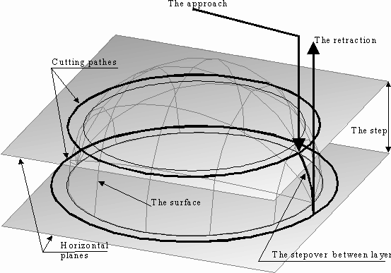
Machining of the model surface is performed using horizontal passes. The step between the passes of neighboring toolpaths can be either fixed or calculated according to the defined height of the scallop.
When using a local coordinate system or a rotary axis, the position of the model being machined will not change, the tool rotation axis is parallel to the Z axis of the local coordinate system, and all work passes are located parallel to the horizontal plane of the same system.
The areas of the model surface being machined can be limited depending on the slope angle of the normal to the Z-axis. If for example, the user needs to machine steep areas with a slope angle of the normal to the Z-axis more than 45 degrees, then it is advised to set the values for the minimum and maximum slope angles to 45 and 90 degrees respectively.
It is also possible to restrict machining of the areas of the restricting model and areas of edges rounding from the resulting toolpath.
Joining of the work passes into a single toolpath can be performed going downwards or upwards. Transition between neighboring work passes can be performed on the surface, using retract and approach moves or via the safe plane.
See also:
Operations for the 3-axes milling