Rotary operation
The rotary machining operation is available if machine has at least one continuous rotary axis. It is used for the machining of the camshafts, crankshafts, worm shafts, paddles, decorate parts and so on.
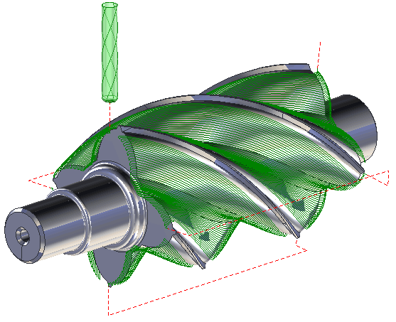
The main peculiarity of the operation is that it uses the 4th rotary axis together with the linear axes. The 5th axis (when it exists) is fixed. Sometimes the 5th axis can be used also.
The <Rotary machining> operation gives the possibility to machine some surfaces of the part or the part as a whole. In the first case the required surfaces must be specified in the job assignment. In the second case the job assignment must be empty.
The workpiece can be defined as the box, cylinder, solid of revolution, rest material, or free-form solid that uses faces and meshes of the geometry model. The operation check on the objects that is specified in the fixtures folder.
The rotary axis position can be defined in the properties inspector that is located as shown in the next picture.
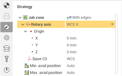
The <Origin> field defines the point that lies on the rotary axis. The orientation group defines the vector of the rotary axis. If the mode is set to the <Along X>, <Along Y> or <Along Z>, then the axis of rotation will be oriented along the corresponding axis of the coordinate system. If mode is <Custom> then axix vector must be defined manually in the fields X,Y,Z of custom direction group.
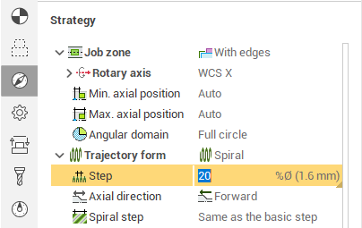
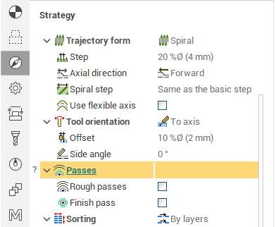
The machining is performed by the series of the passes. The passes can be different shape and located by different ways. The shape and the location of the pass is depended on the Trajectory form that is defined on the strategy folder in the parameters dialog.
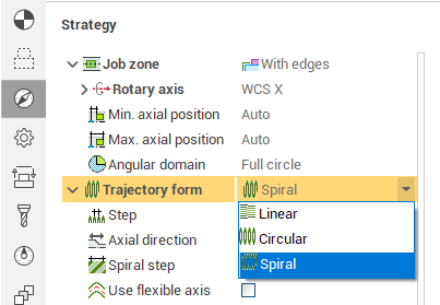
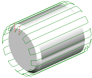
if <Linear> is selected then working tool path is parallel to the axis.
if <Circular> is selected then working tool path lies the plane that is perpendicular to the axis.
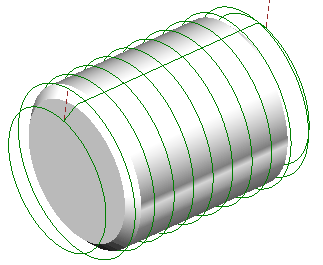
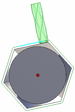
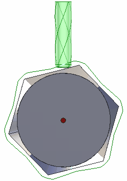
if <Spiral> is selected then working tool path has the helical shape. if the step definition mode is set to the <Same as the basic step>, then the tool path is a one continues helic. The spiral step can be also specified as an absolute value, percents of the tool diameter or the angle in degrees.
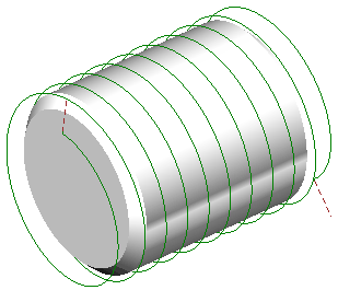
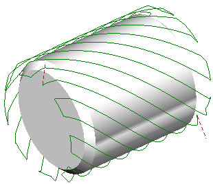
If the <Spiral step> is not equal to the step of machining then tool path is a series of the helical curves The distance between the curves in the series is equal to the machining step. The spiral step value can be positive or negative. The sign defines the torsion direction.
The step on machining is defines on the same page. It can be specified as absolute value or in percents on the tool diameter.
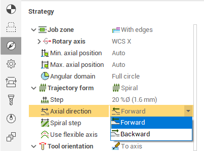
The <Axial direction> defines the order of machining. If the Axial direction is <Forward> then the tool passes is ordered in the rotary axis vector direction else the order is reversed.
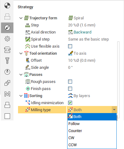
The milling type defines the direction of the part rotation around the rotary axis.
<Both>. The rotation is alternated at every working tool path. It allows to reduce the idle passes and the machining time that is the save.
<Climb>. The part rotation direction depends on the tool rotation. It gives the climb milling type.
<Conventional>. The part rotation direction depends on the tool rotation. It gives the conventional milling type.
<Clockwise>. The part rotation direction does not depends on the tool rotation.
<Counterclockwise>. The part rotation direction does not depends on the tool rotation.
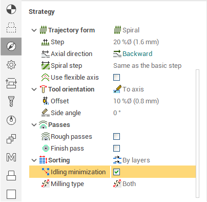
The length of the idle tool path cam be minimized if set the tick in the Idle parameters.
The <Contact tool type> defines the way how the tool axis is calculated.
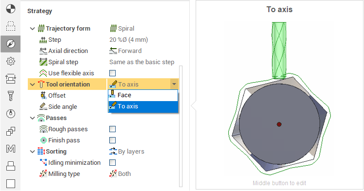
if <Face> is selected then the tool axis is parallel to the surface normal in every tool path point. The <Lead Angle> can be defined additionally. It allows to improve the cutting conditions in the contact point. It can be positive or negative.
if <To axis> is selected then the tool axis is intersect the rotary axis in every tool path point. So the tool axis does not depends on the surface normal. Offset can be specified to improve the cutting conditions. The offset can be defined as absolute value or as the percents of the tool diameter.It can be positive or negative.
|
Tool orientation |
|
|
Face (surface normal) |
To the axis |
|
|
|
The additional rough passes can be defined on the <Radial layers> panel. The number of the passes is calculated using the <Stock> and the <Step>. Step can be defined as the absolute value, percents of the tool diameter or count. If count is selected then step equal to stock divided into count. <Finish pass> tick generates the additional cleanup pass. The stock that is near defines the stock for the last finish tool path.
The stock parameter shifts the rough and finish passes from the surface. It can be positive or negative.
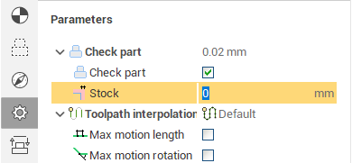
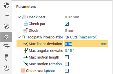
Deviation works like in all milling operations. The higher tolerance the much time need to calculate the tool path.
The roll type and the checked geometry works like in the other milling operations.
The way of the approach to the first point of the working tool path and retract from the last point of the working tool path are defined on the <Lead In/Lead Out> page of the parameters dialog. This page defines the way of the transition between the working passes.
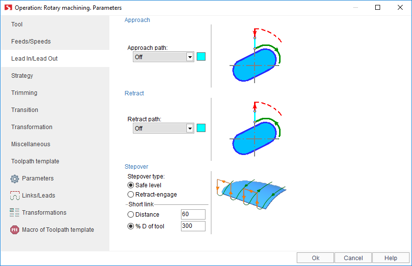
The next approaches and retractions are available:
<None>. The tool goes down/up to the first point of the working tool path without additional engage or retraction.
<Normal>. Additional cut is added to the first or last point of the working tool path. The cut is directed as the surface normal in the current point. The cut length is specified in the <Distance> field.
<Tangent>. Additional cut is added to the first or last point of the working tool path. The cut is directed as tangent to the tool path in the first (last) point. The cut length is specified in the <Distance> field.
<Angle to tangent>. The additional cut is directed under defined angle to the working tool path in first/last point. The cut length is specified in the <Distance> field. The <Angle> is specified in the degrees. It lies in the plane that is perpendicular to the part rotary axis.
<Arc>. The additional arc is added to the first/last point of the working tool path. It lies in the plane that is perpendicular to the part rotary axis. The arc radius is specified in the <Distance> field. The arc sector is specified in the degrees in the <Angle> field. The radius and angle can be positive or negative.
There are three ways of the transition between the subsequent tool passes. The way is defined on the <Stepover> panel.
<The shortest stepover>. This way is used automatically if the distance between the last point of the current pass and the first point of the next pass is less than the value defined in the <Short link> panel. This value can be specified as absolute distance or in the percents of the tool diameter. If the distance is more the than the short link size than the one of the next strategies is used:
<Retract-Engage>. In this case the retraction is added to the end of the current pass and the engage is added to the start of the next pass. The link between the last point of the retraction and the first point of engage is the shortest.
<Safe level>. In this case the link between the last point of the retraction and the first point of engage is performed with the go up to the safe level.
The value of the safe level is defined on the <Transitions> page of the parameters dialog.
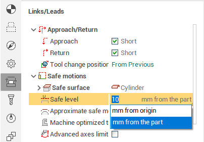
The <Safe level> in the current operation defines the cylinder radius. The axis of the cylinder is equal to the rotary axis. It is assumed that any motions out of this cylinder would not make the collision with the part or fixtures. The safe level can be defined by absolute or increment value. In the first case it is equal to the cylinder radius. In the second case the value is added to the point that is the farthest from the rotary axis.
The tool goes down to the defined level on the rapid feed, after that the tool goes on the approach feed. The level where the feed is changed is defined on the <Feed switch level> panel. This level can be specified as absolute or incremental value. if value is absolute then it is a distance from the rotary axis. if value is incremental then it is a distance from the first point of engage.
The possibility to multiply tool path by axis is available for the rotary machining operation also. It allows to reduce the calculation time if the part elements are repeated.
See also:
Operations for 4-axes and 5-axes milling