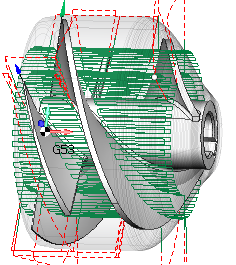
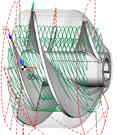
Roughing rotary operation
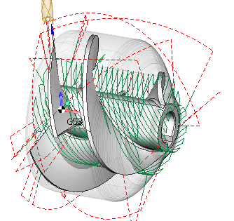
Roughing rotary is a 4 axis toolpath that removes the workpiece material layer by layer. It is similar to the Roughing Waterline except that the machining layers are not planes, but cylinders around the rotary axis.
Rotary axis
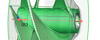
The rotary axis is defined by its origin and direction. You can easily set the desired parameters of the rotary axis both in the inspector and with the mouse in the graphic view.
Job zone
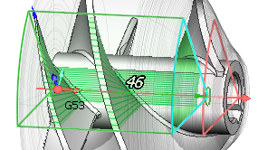
The job zone is defined by:
the minimal and maximal axial positions,
the angular sector,
top and bottom levels of machining.
Machining parameters
The depth step can be set as an exact value as well as the number of layers.
The machining step defines the maximal distance between the machining passes in a layer.
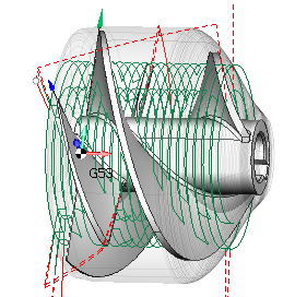
Machining strategies
Currently three strategies are available.
1. Circular
The circular strategy generates passes around the rotary axis that represent 4 axis arcs.
2. Linear
The linear strategy generates passes along the rotary axis that represent linear cuts. The angular step-over between passes on each layer is the same, what means that the real step-over gradually decreases when approaching the bottom layer of machining
3. Spiral
The Spiral strategy generates helical passes. The pattern is well suited for machining parts like screws and impellers.