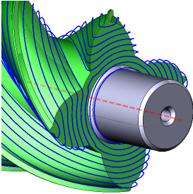
5d surfacing operation
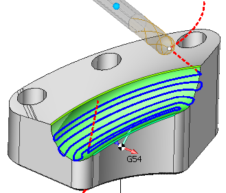
The finishing operation allows the surface to be machined with a variety of strategies (parallel to plane, parallel to curve, morph and others) and tool axis orientation modes (fixed, normal to surface, to rotary axis, through point, through curve, etc).
Typical workflow
1. Create the operation
2. Add the Machining surfaces to the Job assignment
3. Select the toolpath strategy
4. Choose between the tool center and tool contact calculation modes.
5. If needed, change the step-over and/or the toolpath margins.
6. Select the tool axis orientation mode.
7. If required, turn on the roughing passes.
8. Calculate the toolpath.
Comparison of the toolpath based on the center and the tool contact point.
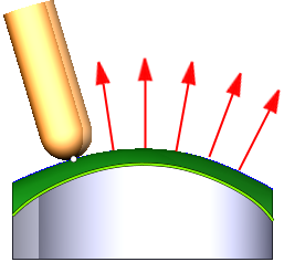
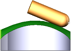
1. Calculation based on tool contact point
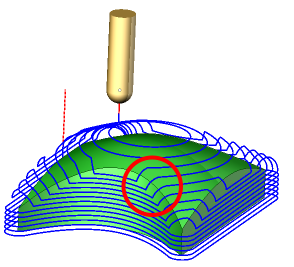
In this mode the work passes are generated by calculating curves on the machining surfaces as the first step and then positioning and orienting the tool relative to the calculated curves in such a way that the point of contact of the tool with a machining surface stays the same. It is desirable, for example, when smooth surfaces are machining, or doing flank milling.
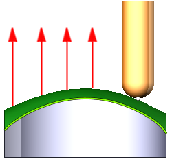
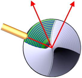
2. Calculation based on tool center
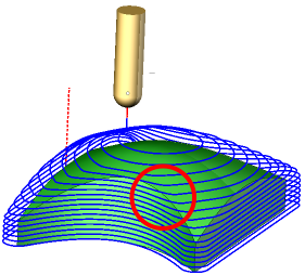
In this mode the work passes are generated in such a way that at first the machining surfaces are being offset either by the tool shape itself for 3 axis machining or by the tool radius along the surface normal for 5 axis machining and only then the sections of the offset surfaces are calculated. For example, for the Parallel to plane strategies it means that the generated work passes all lie on parallel planes. Another advantage of this mode is that not only the surfaces themselves but the edges between machining surfaces are taken into account.
Strategies
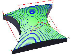
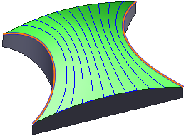
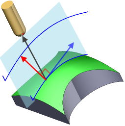
Parallel to plane
The passes are generated as a result of intersection of the machining surfaces and parallel planes surfaces. Three options are to choose from.
1. Parallel to vertical plane
The planes are parallel to the tool axis, as in the Plane toolpath. Additionally the angle of rotation of the planes around the tool axis can be specified.
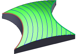
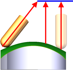
2. Parallel to horizontal plane
The planes are perpendicular to the tool axis, as in the Waterline toolpaths.
3. Parallel to 3d plane
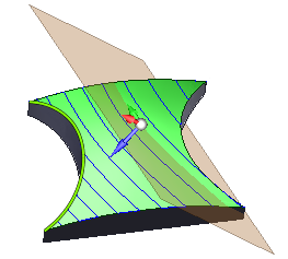
The planes can be freely oriented in space regardless and independently from the tool axis orientation.
Margins
It is possible to limit the generated passes by two points.
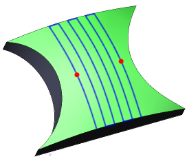
Parallel to curve
The passes are generated by finding points on the machining surfaces that lie on the same distance from the First Curve. Unlike with the Scallop toolpath the step-over between passes is not guaranteed to be constant.
Margins
Use the Start margin to set the starting offset for the first generated pass.
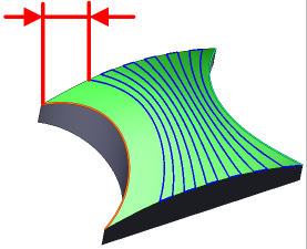
Use the Zone Width to limit the number of generated passes. You can either specify an exact value for the zone width or define the job zone with a point.
Across curve
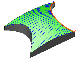
The passes are generated by sectioning the machining surfaces with planes perpendicular to the First curve.
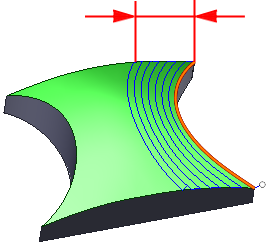
Morph between two curves
The passes are calculated by finding points on the machining surfaces which satisfy the criteria that the ratio of the distance from the given surface point to the First curve to the distance from the point to the second curve stays the same for a given pass.
Margins
Use the Start margin and the End margin to set the offsets from the generated passes to the First and the Second curves respectively.
Around rotary axis
The passes are calculated as sections of the machining surfaces with the series of cylinders around the rotary axis.
Tool axis orientation modes
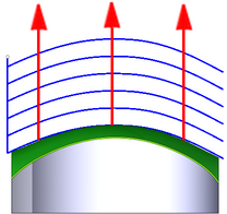
Fixed
In this mode the tool axis orientation stays the same for the entire toolpath (unless the vertical clearance angle is specified). Basically what you get is a conventional 3 axis milling toolpath.
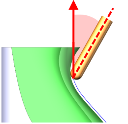
The Vertical clearance angle feature automatically tilts the tool away from the wall surfaces in places where the slope of a surface is steep or negative (a surface normal looks down the tool axis). An additional clearance angle can be used. It allows simple machining of undercut areas.
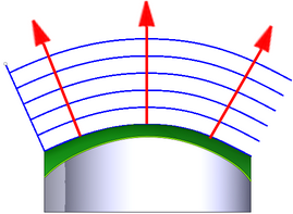
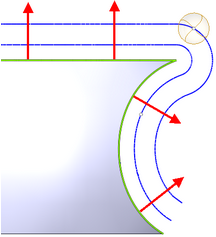
Normal to surface
The tool is oriented by normal to machining surfaces. Additionally the lead and lean tool angles can be applied to further tilt the tool along or to the side from the cutting direction.
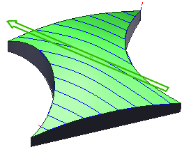
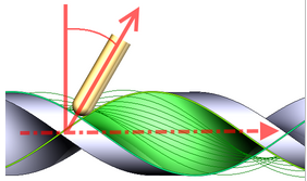
Flank
The tool contacts machining surfaces with the peripheral part (cylindrical part for the cylindrical mills). Additionally lead and lean angles can be applied. The strategy can be used for swarf milling.
Through point
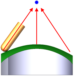
The tool axis is oriented to the specified point.
Through curve
The tool axis is oriented to the nearest point of the specified Tilt curve.
To rotary axis
The tool axis is directed to the rotary axis, as in the rotary machining. Additionally the side angle to the rotary axis can be specified
4 axis machining with the Rotary axis
The rotary axis feature allows to transform a 5 axis toolpath into a 4 axis toolpath by locking one of the components (X, Y, Z) of the tool axis direction.
Job assignment
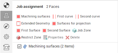
Machining surfaces
The machining surfaces define where the toolpath will be calculated
First curve
The First curve is used in the Parallel to curve strategy to define the curves parallel to which the passes are calculated and in the Morph between two curves strategy to define the first curve. You can select one or more not necessary connected curves or edges as the First curve.
Second curve
The Second curve is used in the Morph between two curves strategy. You can select one or more not necessary connected curves or edges as the second curve.
Tilt curve
The tilt curve is used for the Through curve tool axis orientation mode.
Job zone
Use the job zone to trim the passes outside the specified 2d containment areas. The plane of the containment area is defined by the initial tool orientation.
Restring zone
Use restrict zones to easily create restriction geometry from curves and edges.
Gouge control
By default the Check part option is enabled. It means that the operation generates a gouge-free toolpath. Often when the geometry of the machining surfaces is simple and the minimal curvature of the machining surfaces is larger than the tool radius you can disable the Check part option to speed up the toolpath generation.
Roughing
Enabling the roughing option turns on the roughing passes. The number of layers and the step between layers can be set. The Check workpiece option can be used to eliminate air cutting.
There are several different modes of calculation of the roughing passes.
1. By surface normal
The roughing passes are calculated as offsets from the finishing passes along the surface normal.
2. Along tool axis
The roughing passes are calculated by simple shift of the finishing passes along the tool axis.
3. In tool plane
The roughing passes are calculated as offsets from the finishing passes in the frontal tool direction. It works best for the parallel to vertical plane strategy and when machining surfaces with the front of the tool.
4. Perpendicular to tool axis
The roughing passes are calculated as offsets of the finishing passes in the plane perpendicular to the tool axis. The mode works better for the parallel to horizontal plane strategy, and when machining surfaces with the peripheral part of the tool.