5D contour and 6D contour operations
5D and 6D contour operations are designed to generate the continues 5-axis tool path. There are few ways to generate the toolpath depends on the way that job assignment is set:
The passes along the curves that is lie on the part surface.
The passes along the isoparametric curves of the defined surfaces..
The tool, the feeds and speeds, the lead-in and lead-out are defined like in all other milling operations. The way of the rough passes generation and the way of its joining are defined on the strategy page of the parameters dialog.
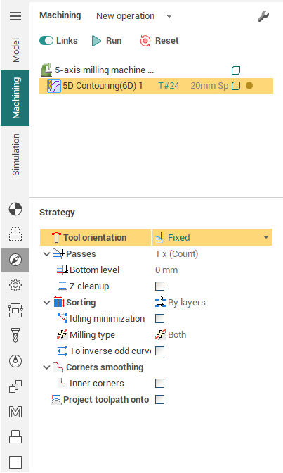
The <Levels> and <Z cleanup parameters> panels allows to generate the additional rough passes under every finishing pass. The <Bottom level> defines the distance from the machined surface. If the value is positive then the tool will undercut the surface. if the value is negative then the tool will over-cut the surface. The <Top level> defines the maximal stock that must be removed by the rough passes. The <Step> defines the layer thickness that is removed at one pass. The <Cleanup height> defines the stock that must be removed at the finishing pass. The <Stock> allows to move both rough and finishing passes from the machined surface. The positive value move the passes away from the surface. The negative value move the passes near to the surface.
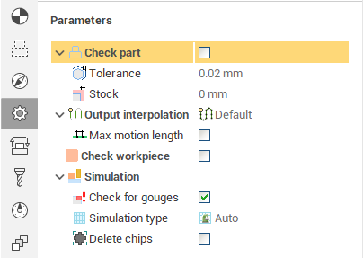
The deviation defines the <Tolerance> of the tool path approximation.
<Milling type> defines the passes joining strategy. In <Climb> mode the machining direction depends on the curves and surfaces. In the <Conventional> mode all passes are inverted. The <Both> mode makes the zigzag tool path.
Sometimes the loops are appear inside the pass. These collision is not checked by default. It's needed to set the <Check part> tick to control the loops. In this case every point of the tool path will be checked. If the path segment is over-cut the part then it will be excluded from the resulted tool path. The <Check workpiece> works like in other mill operations.
The way how to generate the transitions between the passes is defined on the transition folder.
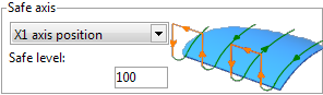
The safe axis is one of the main parameters. It defines the axis name and position, where the rapid motions can be performed. For example if the Axis X is selected and the value equal 100 then it means that the safe plane can be defined as X=100. Parameters <Step-over type> and <Short link> work like in other mill operations.
See also:
Operations for 4-axes and 5-axes milling
5-axis milling along the isoparametric curves
5-axis milling of the profile on the surface
5-axis milling of the ruled surfaces by the flank of the mill