Approach and retraction of mill operations
To provide more flexibility and control at the start and end of a toolpath, there are several options for tool approach and retraction in the system. Approach moves are added at the beginning of every toolpath, retraction moves are added at the end. Feeds that differ from the work feed can be applied to these moves. If an operation uses cutter radius compensation, then it will be activated at the beginning of an approach move and canceled at the start of the retraction move.
The <Approach> of a tool is performed as follows:
Tool approach to the plunge point at the safe plane for the operation.
The Z-axis rapids to the safe level or safe distance before beginning the approach move (depending on settings). The safe level is measured from the Z top level in the current coordinate system. The safe distance is the Z distance above the pass depth.
The Z-axis feeds down to the beginning of the defined approach.
The user-defined approach is applied to the machined model.
Work pass starts.
<Retraction> of the tool is performed as follows:
End of the work pass.
Retraction of the defined type at the work feed.
Vertical rising of the tool to the safe plane at rapid feed.
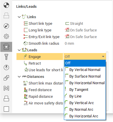
In the system there are the following approach/retraction methods available:
<Without approach>. The approach and retraction toolpath parts is not generated.
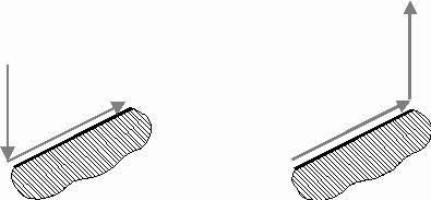
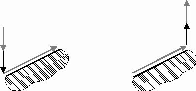
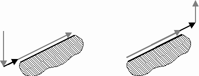
<Vertical>. The approach is performed vertically to the first point of the work pass. The retraction – vertical from the last point of the work pass.
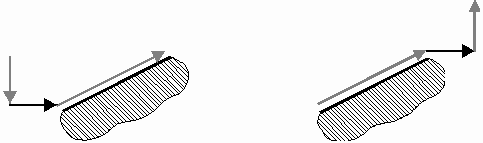
<Horizontal>. The approach is performed horizontal to the first point of the work pass. The retraction – horizontal from the last point of the work pass.
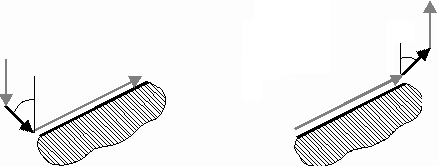
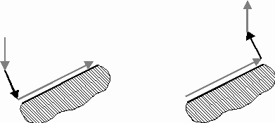
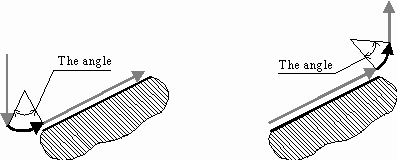
<Angle to Z-axis>. The approach is performed by angle to Z-axis to the first point of the work pass. The retraction – by angle to Z-axis from the last point of the work pass.
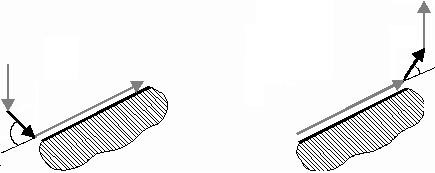
<By normal>. The approach is performed along the normal to surface at the first point of the work pass, the retraction – from the last point
<By tangent>. The approach is performed tangentially to the first machining point and the retraction tangentially from the last point
<Angle to tangent>. The approach is performed by angle to tangent to the first machining point, and the retraction by angle to tangent from the last point
<By arc>. The system adds an arc to the first point on the curve using the defined radius. The arc lies in the vertical plane and is tangent with the first toolpath applied to the contour. The angle of the curve is defined by user. The tool plunge is performed at the vertical end of the arc, and then moves along the arc and then onto the work pass. Retraction is performed in reverse.
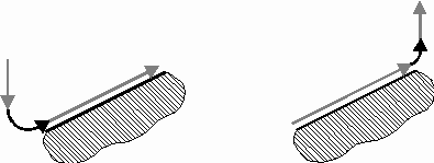
<By arc (Angle)>. The system adds an arc to the first point on the curve using the defined radius. The arc lies in the vertical plane and is tangent with the first toolpath applied to the contour. The angle of the curve is calculated so that the tangent on the other side of the arc is vertical. The tool plunge is performed at the vertical end of the arc, and then moves along the arc and then onto the work pass. Retraction is performed in reverse.
The definitions of the geometrical parameters for approach moves are made in the <Lead In/Lead Out> page in the <Operation parameters> window.
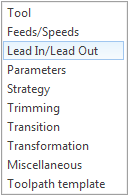
The page opens by pressing the <Parameters> button. In the schematic pictures the rapid toolpath is marked in red, work feeds in green. The required type of approach and retraction moves for an operation can be selected in this view. Depending on which type of approach/retraction is selected, the system updates the graphic and the fields for the parameters of the selected type. Dimensions of moves can be specified either in the current units of the system (mm or inches), or a percentage of the tool diameter. Way to specify the value switches buttons next to the input field.
Quick-clicking the left mouse button on the button switches the way to the next immediately. If when you press you hold the button release on the half-second, then a context menu appears, where you can select the desired method of setting value.
By using the <Safe level/Safe dist> options, the user can define the method for the tool to change from rapid to feed. The safe level is defined by the Z datum of the current coordinate system. The safe distance is defined relative to the approach of the defined type at the work pass height.
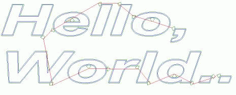
When machining 2D curves, the system performs automatic selection of the approach point. If the approach point is not defined, then approach will be performed at an outer corner or on the longest section as shown in the picture below.
See also:
Approach, retraction, and plunge methods