Visibility panel
The visibility panel is aimed to manage visibility and visualization parameters of objects for different working modes individually (Model, Machining, Simulation).
The panel contains buttons to control visibility of:


 Tool holder

Machine
 Tool path


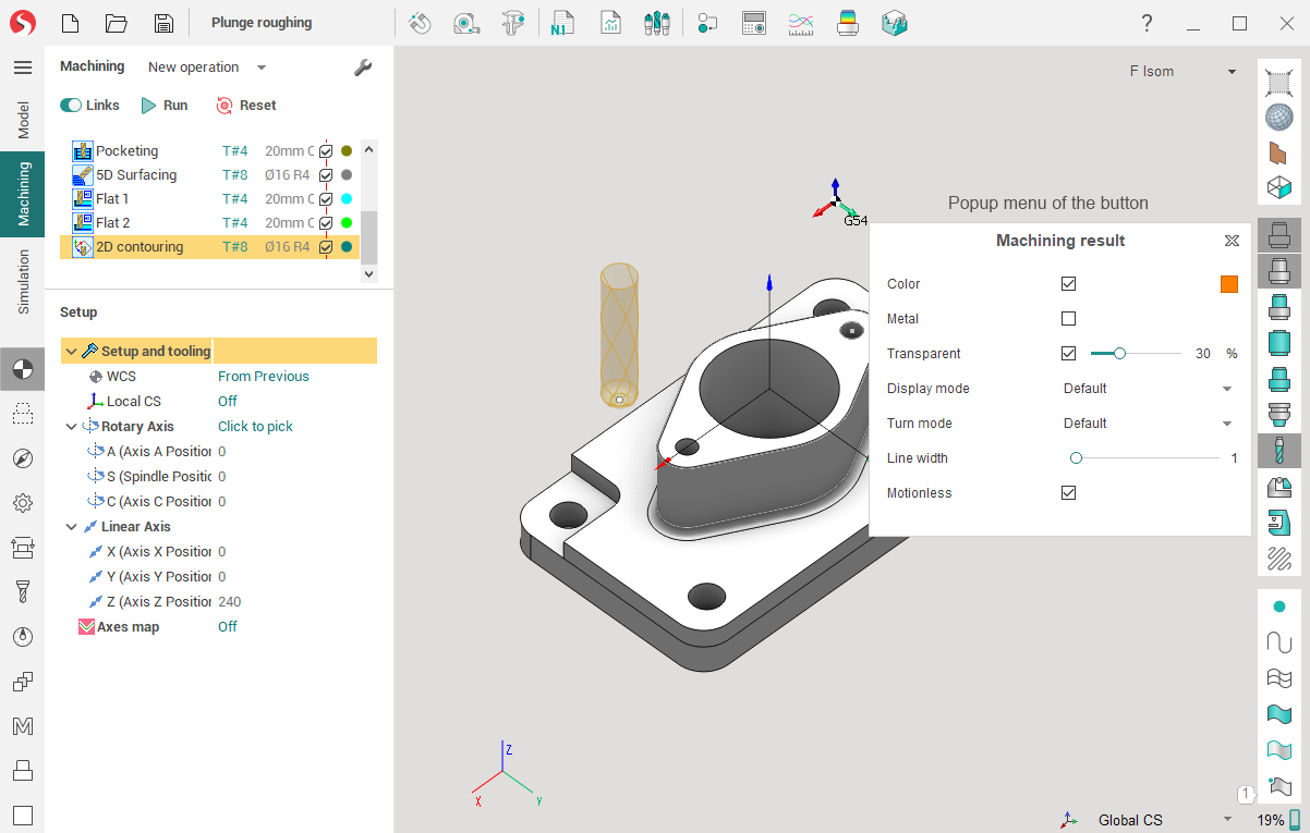
The button pressing by the left mouse button switches visibility on or off for the corresponding object. But the right mouse button click on the same button opens a pop-up menu to change visualization properties of the object.
The pop-up menu can contain the following items (vary depend on item type):
Color – switches how to draw the object: by one selected color or by different colors (subject to the tool trace for simulation for example). Click to colored box to select color.
Transparent – the object will be drawn as transparent if the option is selected but as solid otherwise. The transparence extent can be defined in the <Transparence> trackbar.
Metallic – turns on the metallic reflection for the object faces.
Woody – turns on the woody reflection for the machining result only.
Display mode – switches the visualization mode for the object (wire, shade, shade with edges and default) The Default item means that the object drawing mode is associated with the main drawing mode which is set by the
 buttons on the Visualization control toolbar.
Turn mode - switches the drawing method for revolution bodies of the object (3D, 3/4, 1/2, 2D and default). The Default item means that the object drawing mode is associated with the main drawing mode which is set by the
 button on the Visualization control toolbar.
Line width - defines the width of the line to paint edges and lines of exact object.
Show points - for toolpath only. Allows to visualize points at the end of each toolpath block.
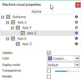
Machine interactive - for the Machine button only. It provides the ability to interactive control the machine nodes and change its visualization parameters.
Change machine nodes - The Machine visual properties dialog will appear where you can setup visual settings for each machine node individually.
Visibility and visualization properties of objects are defined separately for each of working modes of SprutCAM X. The <Machining result> button controls the workpiece which is machined for the <Simulation> mode but for other modes the same button manages visualization parameters of the machining result of the current operation (or of the full technological process if there is not any selected operation).
The object visualization settings are saved in the SprutCAM X configuration file and they are loaded for every execution of the application.
See also: