Interactive Machine
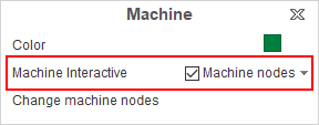
System provides the ability to interactive machine control and change its visualization parameters. To enable or disable this feature you use special item in the pop menu of machine visibility button:

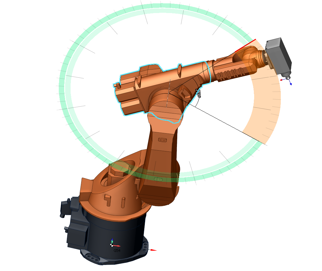
Machine components under the cursor will be highlighted. Dotted line shows the rotation axis for rotary axes. After click on any machine node visual parameters window will be shown:

1 - Node name;
2 - Current position of axis. You can type wanted value or use mouse wheel to set it. This field will be shown only for movable machine nodes;
3 - Machine node color. Click to show Select Color dialog;
4 - Machine node visibility;
5 - Switch to "Ghost mode". In this mode only invisible nodes will be shown;
6 - Machine node painting mode (Wire, Shade, Edge-Shade);
7 - Turn on metallic mode;
8 - Machine node transparent;
9 - Machine node transparency.
It is possible to move machine nodes position using drag-and-drop. If node is not movable, nearest movable parent will be moved. For rotary nodes auxiliary circle, showing rotation plane, will be shown. The radius of the circle is equal to the distance from the axis of rotation to the point of clicking on machine node:

It is also possible to set whole machine position by setting wanted tool position. Machine will change position of nodes to provide wanted tool position. Drag-and-drop tool to use this feature. If machine has not active tool, yellow point will be shown instead. The tool moves along view plane, so set view vector along axes X,Y,Z for detailed control.
See also:
Graphic window and visualization control
Video example about interactive machine