Compound approaches and retractions of mill operations
An approach move is performed in the same plane as the contour being machined. An approach move is a part of the machining toolpath, which is added to the starting point of the contour being machined. It can consist of three areas – toolpath inclusion area, the approach area itself and the area that represents an add-on to the contour being machined. Using these three methods, the user can obtain an optimal approach toolpath in every case.
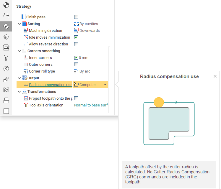
Activation of tool radius compensation
The activation and cancellation of cutter radius compensation can only be performed on linear tool movements, as either a tangent or normal (perpendicular) move to the next toolpath move, or from an arbitrary point. Immediately following the compensation activation area of the toolpath, there can be either an approach area, or a contour extension area, or the contour itself, depending on the conditions and options selected by the user. The compensation activation area is used to define the linear move in the NC code that is used to apply cutter radius compensation. It would also include the <G41> or <G42> commands as well as the offset numbers used (usually defined with a <D> or <H>). The tools used to define these parameters are found on the <Toolpath> page. Using the options in the <Compensation switch cut> area, the user can select the required method for applying the cutter compensation for the CNC control. The length of this move can be defined in the <Distance> field. In the "Use" combo box is selected in some cases it is need to add the compensation switch cut. There are several options.
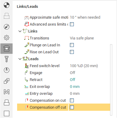
When compensation is on. Compensation switch cut is added to the toolpath only if you've enabled the tool radius correction. Correction can be enabled or disabled for the entire operation on the "Lead In/Lead Out" page with an appropriate switch. To enable the correction you should also set the Use compensation flag for the specific contour in the Job assignment window.
Never. Compensation switch cut will not be added.
Always. Compensation switch cut will always be added, even if the tool radius correction is turned off.
The compensation activation area is formed by the Milling unit's drive system; the older units form a simple linear transition, more modern CNCs can create a toolpath with control over tool contact with the workpiece.
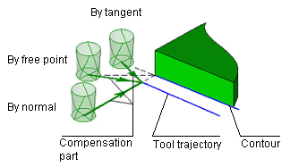
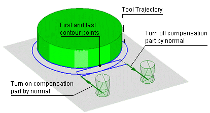
The picture below shows the available methods for the additional moves required for applying cutter radius compensation. These moves are joined to the start of the toolpath. In this picture the approach and additional approach moves are not used. The dashed lines show the tangent, arbitrary and normal (perpendicular) methods of compensation application moves. The lines with arrows are the toolpaths that will be produced at the CNC machine based on the radius value of the tool that is entered into the CNC control by the operator.
Approach
Rather than plunge the tool into the workpiece at the start point on a contour, it is possible to add an approach move. The choices are none, tangent, normal and from start point. This approach path would connect directly to the contour itself, or, if an <Additional approach> move is selected it will connect to this. If a <Compensation switch cut> is also selected, then this move will be added before the approach move, and the compensation command will be output in the NC code. Accordingly, if compensation activation (Model page) was not activated, then the tool will follow the center of the approach curve. The approach can be defined in the <Toolpath> window. In the <Approach path> field, the user can choose the approach type: <Without approach>, <Arc>, <Normal>, <Tangent>, <Angle to tangent>.
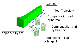
The picture below shows an arc approach move. The end of the arc touches the models contour. Actually, the approach area forms part of the machining contour. The question of whether to use an approach move or not has to be decided by the user. It depends on the specific conditions and requirements of the model being machined.
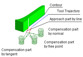
The next picture shows an approach using angle to tangent. This also uses a compensation switch cut as in the example above.
Contour extension area.
It might be required on occasions, to extend either the start of a contour, or the end, or both. To achieve this in SprutCAM X we use the <Additional approach> and/or <Additional retraction> options. An additional approach is added at the start of a contour, additional retraction is added to the end. In general, it is used when machining closed curves, when the start and end points of the contour are coincident. When machining starts and ends at the same point on a contour then a <Witness mark> can be left on the contour. This is due to the uneven loads on the tool due to stock removal.
That extension area can be formed by two methods; either tangent to the starting and the end points or along the contour. When using the <Tangent> mode, one should note that in some cases the tangent can be pointing towards the model and thus take the necessary actions to prevent damage to the model. The additional approach and retraction moves are defined in the <Toolpath> window. In the <Approach type> area the user can choose the approach type: <None>, <Along curve> and <Tangent>.
The picture above shows the situation where the additional approach and retraction areas are defined using the <Tangent> method. The approach and retraction moves are not used and a <Normal> <Compensation switch cut> is being used. An additional tangent move at the end and a normal compensation switch is used to cancel cutter radius compensation.
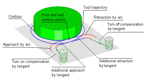
The picture above shows a similar situation to the previous example, but with approach and retraction moves as well.
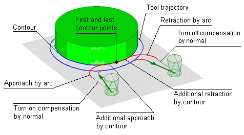
This example has the along contour option selected, the <Additional approach> and <Additional retraction> options are set to <Along curve>.
Tool radius compensation switching.
On Lead In/Lead Out page can enable or disable the use of correction on the tool radius. Depending on the type of operation the panel of correction can change his appearance.
The panel of correction in the contouring operations has a switch that allows you to specify only two options: "correction is on" and "correction is off". If the correction is on, it becomes available input field where you can set the value of the compensation radius. This value does not affect the toolpath calculation and the coordinates displayed in the NC-program. It only sets a value that is used in the simulation mode to simulate the behavior of CNC control. CNC, with the inclusion of correction, shifting tool from the programmed path by an amount specified in the corrector to the tool radius. Compensation radius can be specified either in the current units of the system (mm or inches), or a percentage of the tool diameter.
The correction panel of Waterline and some other operations, has a combo box that contains several possible modes of correction. Depending on the correction mode radius automatically takes either zero or a value equal to the tool radius.
See also:
Approach, retraction, and plunge methods