Job assignment for 2D and 3D curve machining operations
The 2D and the 3D contouring operations are simple, at the same time the powerful cycle for creating planar tool paths based on specified curves, edges, faces or pockets. By defining a <base surface> you can also generate tool paths on cylindrical and revolution surfaces. Using the <Project on part> feature you can project the generated tool path onto the part, and by specifying the <Tool axis orientation> mode you can generate four and five axis tool paths by normal to the part or to the base surface.
Adding new items
In the 2D contouring job assignment you can use the following items: curve, pocket, top level, bottom level and base surface.
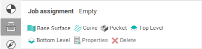
To add a new contour into the job assignment just select curves, edges or vertical faces you want to machine and press the <Curve> button. The connected entities will be joined into contours.
To add a pocket into the job assignment just select either a bottom or a side face of the pocket and press the <Pocket> button. A pocket defines not only the contour, but also top and bottom levels.
You can define top and bottom levels of machining in the Job assignment. Just select a geometry entity in the graphic view and press either the <Top Level> or the <Bottom Level> button.
Contour features
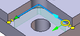
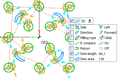
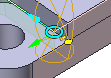
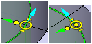
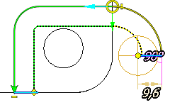
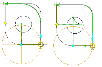
A job assignment item looks like at the pictures below.
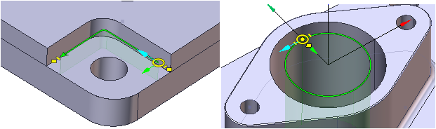
An item consists of the following features.
Contour itself. The bold green line represents the curve which will be output into the CLData.
If a contour is compensated and the <Radius compensation> is set to <Control> than an additional dashed line is displayed, which represents the tool center curve (the curve along which the tool will be moved).

Accessing contour parameters
To access contour parameters just left click on a contour in the graphic view. You will see the action bar.
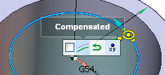
Here you can switch the <Compensated> flag of a contour and its <Machining with return> flag. For closed contours you can also switch the <Fix start point> flag.
Changing parameters of several contours together
To do this you should select several contours and edit parameters of one of them. When you make a change to a parameter of one contour this change applies to all the selected contours. In such a way you can change the <Compensated> flag, the <Machining with return flag>, the <Fix start point> flag, the contour direction, the contour side.
Selecting multiple contours
To select several contours you can hold the [Ctrl] key on the keyboard and select them with the mouse.
To select all contours in the job assignment just double click on any of them in the graphic view.
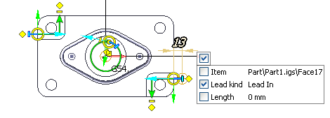
To select contours by some criteria click on a contour, than on the check box in the action bar that appears and check the criteria in the properties tree that appears.
2. Contour start point (yellow circle). To change start point position just drag it with the mouse. You can also change start point position by X and Y dimensions. Just left click on the point and edit the dimensions that appear.
The default start point position for closed contours is <Auto>. It means the position of a point is determined by the operation during toolpath generation. You can distinguish auto start points from regular ones by their visual representation. Auto start points are depicted without yellow dot inside, regular ones points are displayed with a yellow dot inside.
3. Contour terminate point (green arrow for an open contour and yellow dot in the middle of the yellow circle for a closed contour). You can drag the terminate point with the mouse, and you can change its position by X, Y dimensions.
4. Contour direction. This is an aqua colored arrow attached to the start point at the above images. To change the contour direction just click on this arrow. The direction arrow can be of two colors: the aqua and the orange. The color of the direction arrow indicates milling mode of a contour, It's aqua for climb milling contours and orange for conventional milling contours.
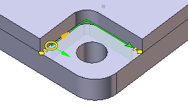
5. Contour side of machining. This is a lime arrow attached to the contour start point at the images above. To change the side of machining just click on this arrow.

6. Contour overlaps. These are yellow dashes next to contour start and terminate points at the images above. An overlap is used to extend a toolpath beyond the contour itself. To change the overlap value you can either drag the yellow dash with the mouse or click on it and edit the dimension value which appears.
Editing multiple overlaps in one click
You should know that when you edit an overlap parameter this change applies to all the selected overlaps. To make the process of editing multiple overlaps quick and simple SprutCAM automatically highlights and selects all identical overlaps. However you can always disable this feature. Just click on the magic wand button at the top of the graphic view.

To select overlaps by a criteria you should click on one overlap, than on the check box in the action bar which appears and check the criteria on which you want select overlaps.
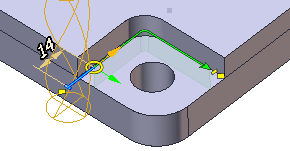
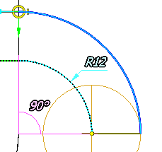
7. Contour leads. These are yellow diamonds at the above pictures. To change a lead just drag the corresponding diamond with the mouse. After that you can edit lead dimensions that appear.
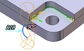
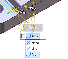
There are three lead types available: none, line and arc. To change a lead type, left click on a lead and select the lead type from the action bar that appears.
For compensated contours and <Control> radius compensation an additional dashed line is displayed. This line represents the tool center curve. Lead dimensions are specified for the tool center curve. This makes lead parameters independent of the current compensation type. If you want to change the size of a compensated lead using drag and drop action you should click on the yellow dot where the tool center curve is ending, and not where the uncompensated lead curve is ending.
Editing multiple leads in one click
You should know that when you edit a lead parameter this change applies to all selected leads. To make the process of editing multiple leads quick and simple SprutCAM automatically highlights and selects all identical leads. You can disable this behavior by clicking on the magic wand button at the top of the graphic view. To select only one lead you should click on it twice. To select leads by a criteria you should click on one lead, than on the check box in the action bar which appears and check the criteria on which you want select leads.
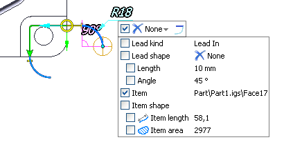
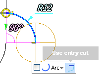
8. Contour entry lines. Entry lines are automatically added to the leads of the compensated contours when the <Compensation type> is other than <Computer>. They play the role of compensation switch lines. Entry lines are not added to leads by line, as that makes no sense. But you can also switch entry lines explicitly by clicking on a lead and checking the <Use entry line> button in the action bar that appears.
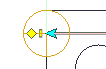
Here is an example of entry lines with <Control> radius compensation.
Contour offsetting/radius compensation
Contour radius compensation is generally used when you have a part line curve (e.g. an edge or a face of a vertical wall) and want to machine material from a side of this part line. To turn the contour radius compensation on just select a contour in the graphic view and click the <Compensated> button in the action bar that appears.

The tool maximal radius is used by default as the contour offset radius. But you also can specify the tool contact point explicitly in the Tool parameters.
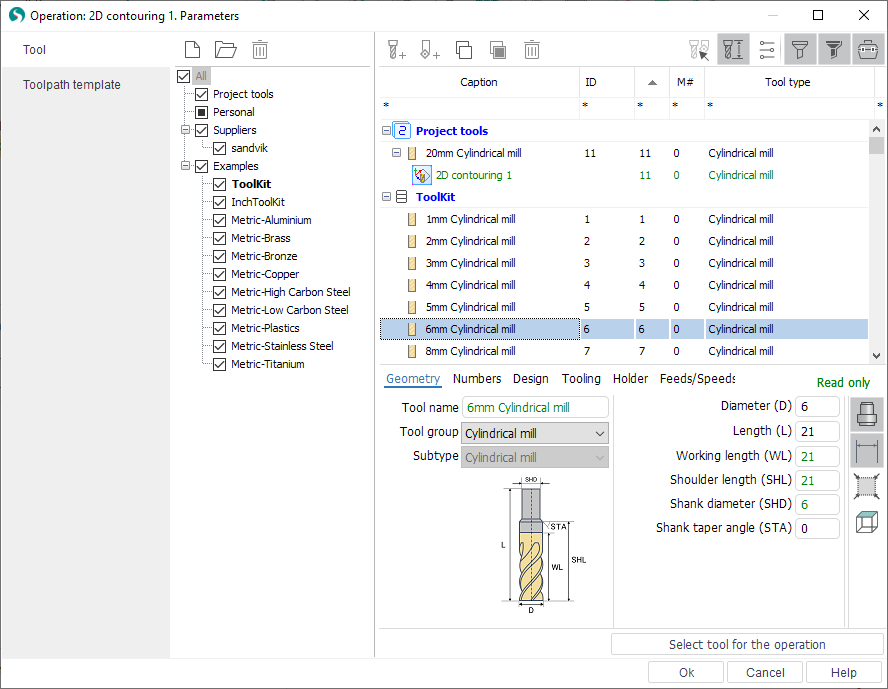
In that case the contour offset distance will be taken from the tool contact point.
The method of radius compensation is determined by the operation parameter <Radius compensation>. You can select it either in the parameters inspector or in the operation parameters windows.
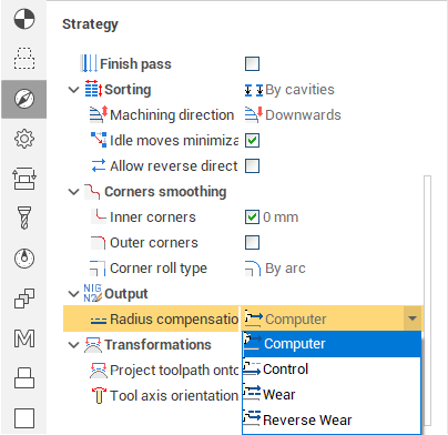
There are four types of radius compensation: Computer, Control, Wear, and Reverse Wear.
Computer radius compensation. When compensation type is computer SprutCAM offsets contours by the compensation radius and outputs them into the CLData. This method of radius compensation is most robust, as SprutCAM automatically removes all the loops and self intersections from the contour offset curves.
Control radius compensation means that the used CNC control is capable of doing radius compensation itself and SprutCAM should output into the CLData not the tool center curves but the part line curves. SprutCAM also generates compensation switch commands (G41, G42, G40 in terms of G-codes) in this mode. This method is generally used when you don't know what tool diameter will be used on the shop floor. But this method has also its shortcomings, as not all contours can be successfully compensated by a CNC control. To make this process more robust, SprutCAM automatically rounds all internal corners of compensated contours with the used compensation radius value. This behavior is controlled by the <Inner corners smoothing> parameter.
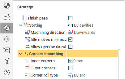
By default <Inner corners smoothing> is enabled and is equal to 0 mm. The corner smoothing values are specified for the tool center curves, so when the control radius compensation is used SprutCAM smooths contours with the radius you set in the box plus the compensation radius. To output unmodified contours into CLData just disable the Inner corners smoothing option.
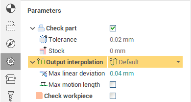
To delete the noise from the output contours and improve the stability of control radius compensation you can also interpolate contours by enabling <Arc interpolation>.
The <Wear> and <Reverse wear> radius compensation types are combinations of the <Computer> and <Control> radius compensation methods. SprutCAM outputs tool center curves into the CLData and generates compensation switch commands. These settings are generally used if you want to accommodate the tool wear on the shop floor. When using <Wear> radius compensation SprutCAM generates "inverted" compensation switch commands (G42 instead of G41 and vice verse). This allows you to use a smaller tool on the shop floor than you specify in SprutCAM (A mill becomes thinner and smaller due to wearing). The <Reverse wear> compensation method can be used as replacement of the <Control> radius compensation, but in that case on the shop floor you can use only tools which are bigger than the tool you used in SprutCAM.
See also: