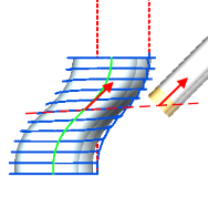
Cladding 5D operation
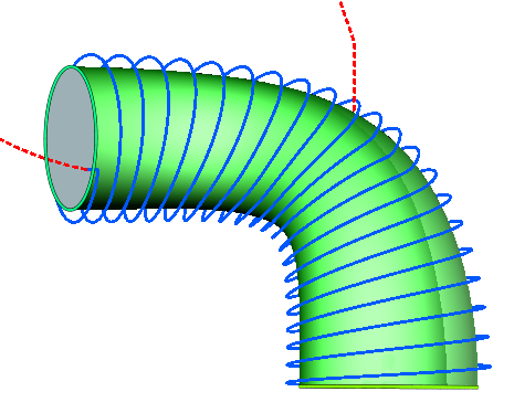
Operation "Cladding 5D" allows to increase material layer on the surface of a detail using strategies from "5d surfacing operation" operation, because this operation is based on it.
Two new strategies in addition to existing were added to the list:
Spiral between two curves
Spiral between two surfaces
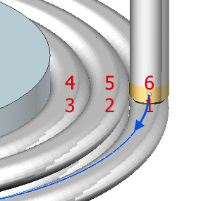
To obtain spiral trajectories, preliminary passes are first generated, similar to the “Morphing” strategy from the “5d surfacing operation” operation. Then the chain of closed passages is transformed into spiral.
The thickness of the layer in simulation defined by the "Working length" property of the tool.
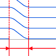
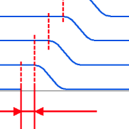
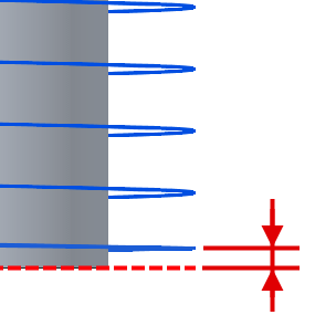
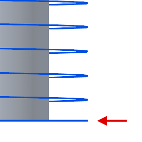
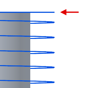
Added special parameters for toolpath modification to avoid several tool passes in one point. It allows better start/finish zones allocation and leads to better surface quality. These options are not available in spiral strategies:
|
Gap for overlappnig avoidance |
Start point offset(in the tab Links/Leads) |
|
It allows to avoid the passage of the tool in the same place several times, as a result of which the height of layer can exceed the specified size. For this, the toolpath is shortened at the end of each curve by the specified value. |
The start point shift relative to the previous layer allows to get a more even distribution of zones where the feed of material starts/stops and where the quality of the formed surface is usually lower. |
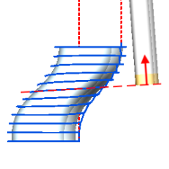
In order to minimize altering tool normals during cladding, added strategies for Tool orientation: "Perpendicular to pass plane" and "Along curve", which set the normals relative to the median plane of the tool passes.
These strategies sets tool normal vector in reference to average pass plane.
Perpendicular to pass plane |
Along curve |
|
|
The tool orientation is set along the tangent to tilt curve in point where it intersects with the middle plane of the pass. |
Additional passes allows to set specific machining conditions for initial and last layers: the height of cladding and the feed of the layer (on the feed page)
First step |
First planar pass(for spiral strategies) |
Final planar pass(for spiral strategies) |
|
The first layer will be executed with the specified step. It may be necessary, for example, to provide better adhesion to the substrate |
Before the ascending spiral, a complete pass will be made along the curve in the initial plane |
Spiral will be finish along the curve in the final plane |
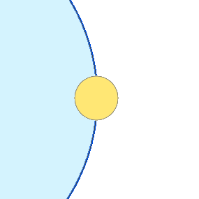
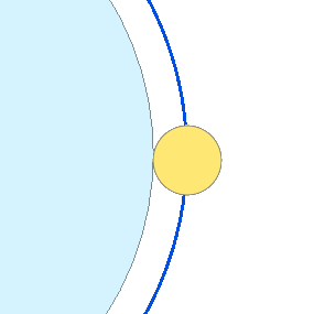
Offset job surfaces allows to disable the trajectory offset by the tool radius
|
The trajectory will pass by the model |
Trajectory with considering the tool radius |
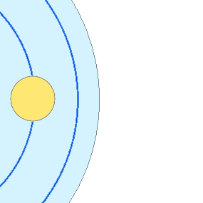
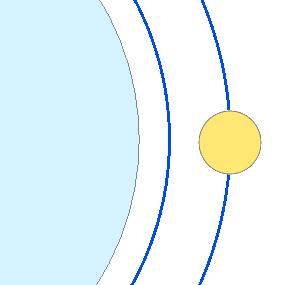
Cladding side allows to choose the side of cladding
Inside |
Outside |
|
The toolpath is built inside the job assignment |
The toolpath is built outside of the job assignment |
Added the following options to Roughing passes:
|
The alternation of the order of passes between the layers (Zigzag) |
|
It can help to get the toolpath without breaks, i.e. without having to switch off the feed of the material and transition on the rapid feed. |
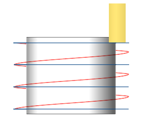
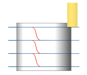
In spiral strategies for smoothing between layers in roughing passes, you can use the following options (only for Zigzag mode):
|
Spiral |
Smooth |
|
Adds a spiral pass between the layers. |
Produces a smooth transition between layers. In order to avoid tool passing in the same place, the parameter Smoothing distance is used. |
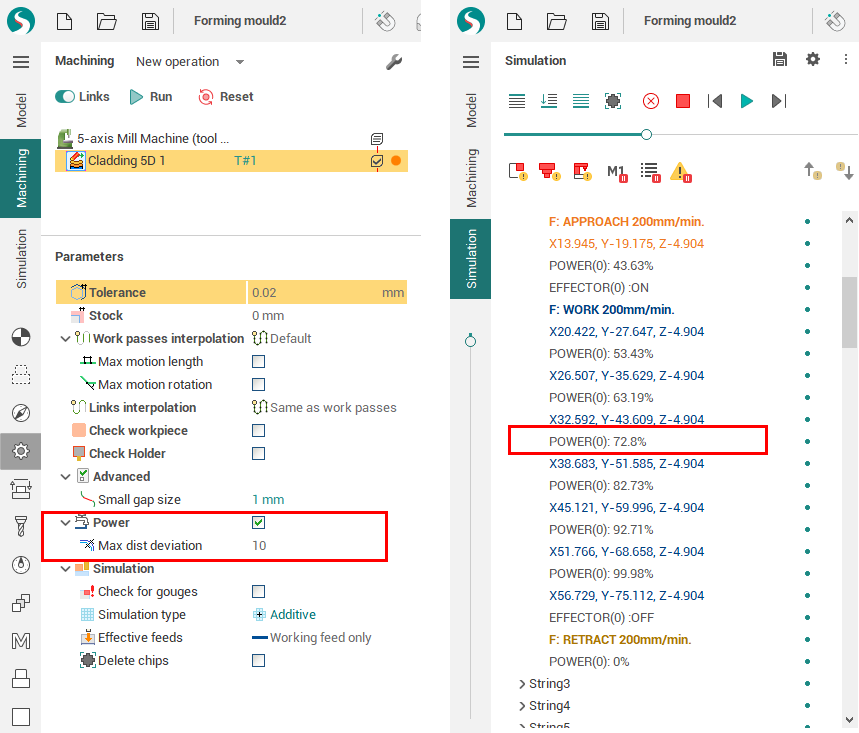
Option "Power"
This option allows you to change the speed of the extruder depending on the height of the layer.
See also: