Curve cladding operation
Additive operations that generates toolpath along curves defined inside job assignment from the bottom to top. It is useful for thin-walled models. Source curves can be placed on a plane, cylinder or body of revolution. And when the "Project toolpath onto the part" option is enabled, cladding in general can be made on the surface of an arbitrary shape. It can generate layer by layer like toolpath or helix spiral.
The Job assignment window shown below.
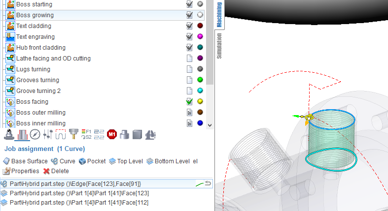
The first task is a base surface definition on which cladding will be performed. To do this, click on "Base surface" button and then select desired surface on the screen. It can be plane, cylinder or body of revolution. The system automatically fills needed options, but if desired you can adjust the properties of the base surface, and then click "Yes."
Now, to specify the local geometry, select the curves on the screen or edges of 3D model along the perimeter of desired area and add them by clicking "Curve" button. To limit the upper and lower levels you should select on the screen any geometrical element, lying at the desired level, and then press the "Top level" or "Bottom level" button respectively. The upper and lower levels you can set also by numerical values in the Properties inspector window.
In addition to the levels in the Properties inspector may be set the following parameters.
Depth step. It determines how many layers of material it should make from the lower to the upper level. You can specify it in current system units (mm or inch), in percents of tool working length or directly specify the number of layers and the step will be calculated automatically.
Initial depth. The depth of first level.
Rough passes at the level. Wall thickness and step should be defined if it is enabled.
Step. Stepover between passes in the current system units (mm, inch), in percents of tool diameter (diameter of melting spot).
Helical machining. If disabled toolpath will consist set of planar levels. If enabled then toolpath for each curve of job assignment will continuous spiral curve.
Initial level of helical machining defines necessary or not to do starting planar pass before rising path.
Idle moves minimization defines the order of transitions between curves. If disabled the curves will be machined in order that they placed in list. If enabled then minimization of intermediate transitions will performed and the order can vary.
Allow reverse direction. It determines whether or not to change the direction of machining along the curve.
Arc interpolation. It tries to interpolate toolpath by circular arcs with defined tolerance.
Project toolpath onto the part. Allows to make cladding on the surfaces of complex geometric shapes. The initial toolpath formed on the base surface is projected onto the 3D model that is specified as the part of the operation.
Tool axis orientation. Available variants: fixed, normal to surface 4D, normal to surface 5D, normal to base surface. Determines the law of the tool axis orientation calculation at the each point. If "fixed" selected, then orientation remain unchanged, same with the Z axis of operation's coordinate system. "Normal to surface 4D" - normal is taken from the part, but the slope will be considered along of one of the rotary axes only. "Normal to surface 5D" - tool axis coincides with the normal to the part. "Normal to base surface" - the normal orientation will taken from defined base surface.
Safe level. Defines the level where long rapid motions it should perform.
Short link max distance. Determines the distance above which the transition will be considered as long.
Short link type, Long link type. Available variants: Straight, Via safe level. The way of link motions.
Neighbor pass links on rapid. If it is disabled, then transition between neighbor passes will perform on working feed (with the supply of weldable material, activated burner, laser, etc.). When disabled, the link will on rapid feed, that is without melting the material.
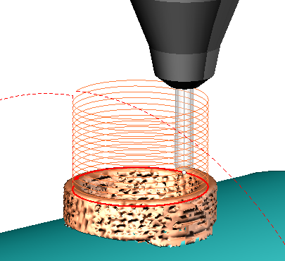
Then you can switch to the Simulation mode to see how the material is added to the place where the tip of the tool is touching the workpiece. The thickness of the layer in simulation defined by the working length property of the tool, or if it is not set (more than the tool diameter), the thickness will equal to the tool diameter.
See also: