Area cladding operation
Area cladding operation designed to add a layer of material on a local piece of the part that can be limited by curves. The user interface and job assignment of the operation is similar to the Pocketing operation. The Job assignment window shown below.
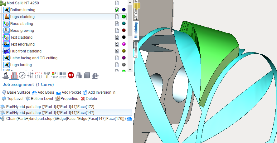
The first task is a base surface definition on which cladding will be performed. To do this, click on "Base surface" button and then select desired surface on the screen. It can be plane, cylinder or body of revolution. The system automatically fills needed options, but if desired you can adjust the properties of the base surface, and then click "Yes."
Now, to specify the local area, select the curves on the screen or edges of 3D model along the perimeter of desired area and add them by clicking "Add boss" button. Similarly pockets (holes) may be add into the previously created bosses. To limit the upper and lower levels you should select on the screen any geometrical element, lying at the desired level, and then press the "Top level" or "Bottom level" button respectively. The upper and lower levels you can set also by numerical values in the Properties inspector window.
In addition to the levels in the Properties inspector may be set the following parameters.
Machining strategy. Parallel and Offset strategies now are realized.
Angle of passes for parallel strategy. If you enable Swap angle between layers it will increase 90 degrees after each layer.
Passes order: Outside to inside, Inside to outside, Zigzag. Defines the order of passes at level from outside to inside or conversely. If Zigzag selected then the order will change from level to level.
Offset pass count for parallel strategy. Allows to enhance the quality of the outer surface. Should be more than zero if you need it.
Offset pass step allows you to set the distance between offset passes. "Offset pass step" is available only when "Offset pass count" is more than 1. There is 3 value: 1) mm (entered value is calculated in mm); 2) %Ø (entered value is a percentage of the tool diameter; 3) % of Step (entered value is a percentage of Step).
Step. Step-over between passes in the current system units (mm, inch), in percents of tool diameter (diameter of melting spot).
Gap to prevent overlapping. In the case when it is making closed contour to prevent overlapping the layers to each other at the connection of the start and the end it is need to leave a gap approximately equal to the diameter of melting spot.
Depth step. It determines how many layers of material it should make from the lower to the upper level. You can specify it in current system units (mm or inch), in percents of tool working length or directly specify the number of layers and the step will be calculated automatically.
Initial depth. The depth of first level.
Machining direction. Available variants: Zigzag, Forward, Backward. If you select Zigzag, the direction will inverted for each next string. Otherwise, all the passes will be executed strictly in a predetermined direction.
Project toolpath onto the part. Allows to make cladding on the surfaces of complex geometric shapes. The initial toolpath formed on the base surface is projected onto the 3D model that is specified as the part of the operation.
Tool axis orientation. Available variants: fixed, normal to surface 4D, normal to surface 5D, normal to base surface. Determines the law of the tool axis orientation calculation at the each point. If "fixed" selected, then orientation remain unchanged, same with the Z axis of operation's coordinate system. "Normal to surface 4D" - normal is taken from the part, but the slope will be considered along of one of the rotary axes only. "Normal to surface 5D" - tool axis coincides with the normal to the part. "Normal to base surface" - the normal orientation will taken from defined base surface.
Safe level. Defines the level where long rapid motions it should perform.
Short link max distance. Determines the distance above which the transition will be considered as long.
Short link type, Long link type. Available variants: Straight, Via safe level. The way of link motions.
Neighbor pass links on rapid. If it is disabled, then transition between neighbor passes will perform on working feed (with the supply of weldable material, activated burner, laser, etc.). When disabled, the link will on rapid feed, that is without melting the material.
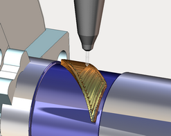
Then you can switch to the Simulation mode to see how the material is added to the place where the tip of the tool is touching the workpiece. The thickness of the layer in simulation defined by the working length property of the tool, or if it is not set (more than the tool diameter), the thickness will equal to the tool diameter.
See also: