Drilling with chip removing cycle (G83, W5DChipRemoving(483))
Drilling with chip removing cycle performs tool motion to the hole center at the <Z return> level and consequent cyclic drill with tool retraction to the <Z safe> level.
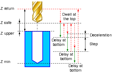
Cycle consists of:
Rapid approach to the hole center at the <Z return> level.
Rapid travel to the <Z safe> level.
Work feedrate motion to the <Step depth S>.
Dwell for the <Delay at the bottom> time.
Rapid return to <Z safe> level.
Dwell for the <Dwell at the top> time.
Rapid motion to the previous depth level, with a <Deceleration (Dcl)>.
Work feedrate to the <Deceleration (Dcl)> with <Step (S)>.
Dwell at for the <Dwell at the bottom> time.
Repeat previous five iterations until the full hole depth is reached.
Rapid tool return to the <Z retract> level.
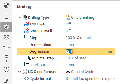
Chip breaking parameters panel defines the step and deceleration. The <Step> can be specified by different ways:
<Distance>. The step is equal to the input value.
<Count>. The value defines the quantity of the tool pecks. The step is calculated as the hole depth divided into the peck count.
<Percent>. The step is specified in the percent of the tool diameter.
If the <Degression> is checked then the depth of every following peck is reduced on the defined value, else the step is constant. The step reduction occurs until its value is not less than <Minimal step>. Minimal step is a percentage of the first step value.
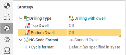
The time of delay is defined on the <Dwell> panel in the field <Bottom dwell>. The time can be specified in seconds or in the numbers of the tool revolutions. In the last case the time is calculated automatically using the defined tool RPM. Delay is absent if the bottom dwell is off.
See also:
The ways of the holes machining