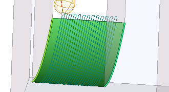
Morph operation
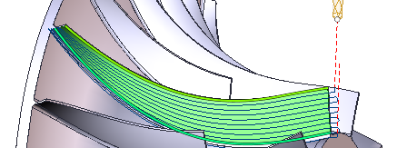
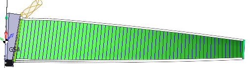
Morph generates passes between two curves. The possible ![]() strategies include:
strategies include:
 Along curves;
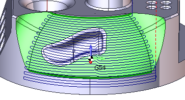
 Across curves;
 Spiral.
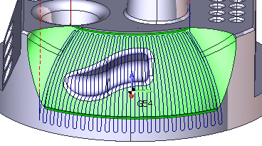
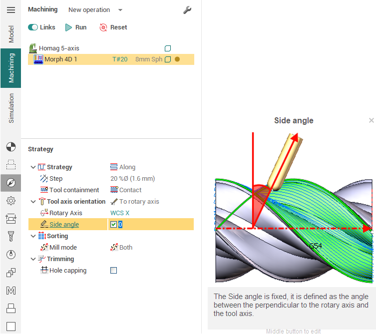
Extensive tool axis orientation modes and tool axis lean options of Morph make it a rather versatile toolpath. The ![]() tool axis orientation modes include:
tool axis orientation modes include:
 Fixed (3d);
 Normal to curves;
 Normal to surfaces;
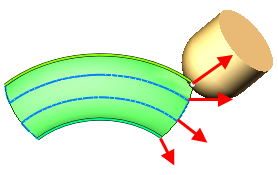
 To rotary axis.
Job assignment
In Morph you have to specify:
 First curve and
  Second curve,
Machining surfaces,
and, optionally,
 sync lines between the first and the second curves.
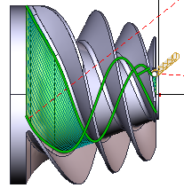
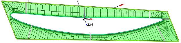
The machining surfaces are used to restrict the area of machining. Morph generates passes only where a tool has contact with those surfaces. Morph generates passes not between
two curves you set in the job assignment, but between two machining surfaces contact curves which are closest to those two curves you specify as the first and the second curve.
Sync lines are used to improve the quality of morphing in difficult cases, especially when machining closed contours. A sync line specify two corresponding points of the first and the second curve.
You can use any types of curves as sync lines: edges, 3d curves, 2d geometry curves. They do not have to connect the points on two curves precisely, so you can draw sync lines at the 2d geometry tab.
Parameters
Parameters of morph are accessible in the parameters inspector. The documentation on parameters is available through the hint. Just click on the question mark next to a parameter and you will see the description of it.
This operation is available for SprutCAM's configurations:
3x Mill
5x Mill
Robot
Expert
Master
Pro