Measurement and analysis
SprutCAM X system incorporates methods to conveniently measure geometrical parameters of the model and to analyze the simulated machining result.

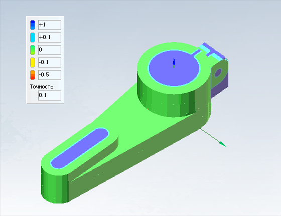
Machining result with part compare can be activated in Machining or Simulation mode. It allows you to display the difference between the original part and the result of machining in the form of a color scheme where each color is associated with a specific deviation range between the compared elements.

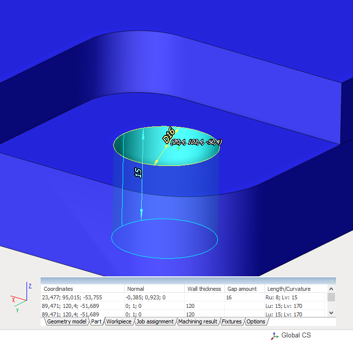
Geometry measuring tool allows you to find out the main geometric dimensions of the object selected in the graphics window. When the mode is activated, an additional window appears in which you can select the type of object being measured (part, workpiece, machining result, etc.) and set additional measurement parameters. Then, when you select an object on the screen, the main dimensions are displayed in the graphics window, and a row with the main parameters associated with the point selected on the screen is added to the measurement window. Some dimensions can depend on the active geometrical coordinate system.
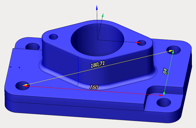
 Measure tool button turns on the mode of measuring distances between two arbitrary points on the screen. After activation, select any two points in the graphics window. Three orthogonal sizes and one diagonal will appear on the screen. The orientation of the dimensions depends on the active geometric coordinate system. Select the following points in pairs to measure others.