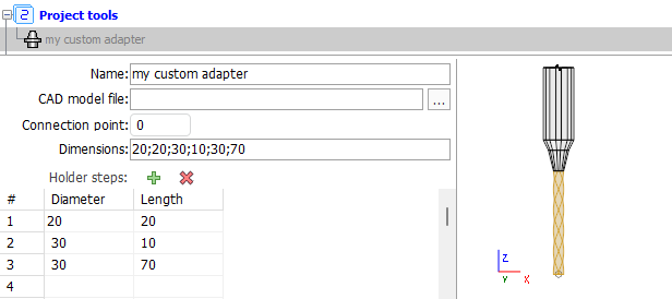
Tool Holder
The tool holder can be defined in two ways: by installing an existing CAD model tool holder and using the SprutCAM builder. The CAD model allows you to specify files in *.stl and *.osd formats. The builder allows you to create custom tool holders with a set of dimensions, defining the diameter and length for each of the steps. Below is an example of how to form a tool holder using a SprutCAM builder:
//C#
//importer is an instance of IMTI_MachiningToolsImportLibrary
var tool = importer.CreateCylindricalMill();
tool.SetName("My Cylindrical Mill Tool with custom tool holder");
var adapter = tool.GetStepsAdapter();
adapter.HolderName = "my custom adapter";
adapter.HolderStepCount=3;
adapter.HolderStepDiameter[0] = 20;
adapter.HolderStepHeight[0] = 20;
adapter.HolderStepDiameter[1] = 30;
adapter.HolderStepHeight[1] = 10;
adapter.HolderStepDiameter[2] = 30;
adapter.HolderStepHeight[2] = 70;
Code execution result:
For turning tools, you can install the holder using the finished CAD model only.