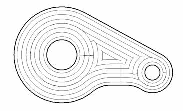
Pocketing

The pocketing operation is used for 2/2.5D machining of pockets and islands, and also for preliminary material removal before engraving operations.
As in the engraving operation , the model being machined is formed from a projection of curves onto the horizontal (XY) plane. The model is created by successive addition of curves or curve groups into the resulting area. Any curve can define the scallop, groove or inverse curve of a defined thickness; closed curves can also be added as ledges, hollows or inverse areas. Additional stock, which will be added to the operation stock , can be assigned separately for every curve or a group of curves. Side edges of the model are not always vertical; the angle of its slope is defined by the value of the side angle. This allows using the pocketing operation for rough material removal before the engraving operation.
The operation performs removal of the entire material, which lies within the model being machined and outside any restricted areas or a workpiece. The workpiece, machining areas and restricted areas are defined by a projection of curves.
The material is removed layer by layer, with assigned step between the layers . Depending on the defined strategy , the material of every layer can be removed by spiral paths, starting from the center working out or from the outside working in. Area clearance using parallel moves can also be used. Transition to the next machining layer can be performed using any of the plunge methods (axial, by spiral, zigzag), or via drill points. A search for an appropriate diameter and depth hole will first be made in the list of operation holes, and then in the open list of holes for the machining process. If no appropriate hole is found, then the system will select coordinates for the hole automatically, using optimum settings. Where possible the coordinates for the center of the new hole, are rounded. If when the operation is created, the hole machining operation was chosen as its prototype, then the list of holes will be copied into the operation and used when searching for appropriate hole for tool plunging.
When using a local coordinate system or a rotary axis , the model being machined is formed from curves projected onto the XY plane of the local coordinate system , machining layers are parallel to the same plane.
If using a profiling tool, the diameter of which gradually decreases towards the end point of the tool (e.g. engraving), then it is possible to use the 3D clearance option for more accurate creation of the side surface of the model simultaneously with material removal.
See also:
Operation for 2/2.5-axes milling