Machine axes control panel
Machine axes control window allows you to watch and modify the current values for all machine / robot coordinates. To show this windows you need to click  button on the main toolbar. It is helpful when analyzing tool path in simulation mode, when constructing of manual approaches or when determining the initial position of the machine to calculate the technological operation.
Visually, the window is divided into several areas. The number of panels and their content may vary depending on the particular machine configuation. The toolbar at the top or left side controls the visibility of these panels.
![]() - The Switch layout button switches the layout of panels between vertical and horizontal.
- The Switch layout button switches the layout of panels between vertical and horizontal.
![]() - The Physical axes panel button shows/hides the panel with the list of physical machine axes.
- The Physical axes panel button shows/hides the panel with the list of physical machine axes.
![]() - The Channel panel visibility button shows/hides the panel with the information about the exact control channel of the machine. There may be several such buttons, depending on the number of channels that a particular machine has. The color of the icon on the button indicates the unique color associated with the channel. All other information in the window will be displayed in this color if it refers specifically to this channel.
- The Channel panel visibility button shows/hides the panel with the information about the exact control channel of the machine. There may be several such buttons, depending on the number of channels that a particular machine has. The color of the icon on the button indicates the unique color associated with the channel. All other information in the window will be displayed in this color if it refers specifically to this channel.
![]() - The States panel visibility button shows/hides the panel which displays a list of stored states of the machine.
- The States panel visibility button shows/hides the panel which displays a list of stored states of the machine.
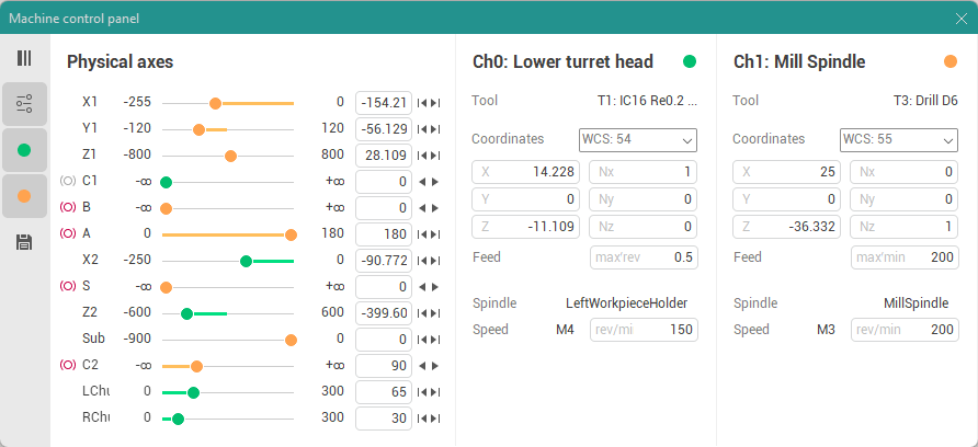
The Channel panel displays the following values.
Color, index and name of the channel.
Active tool numer and name of the channel.
Active WCS number combo where you can also choose some additional coordinate systems to display tool coordinates.
Tool coordinates and orientation angles, vector or quaternion in the specified spatial CS. Orientation angles type can vary depend on exact machine schema settings.
Current feed value and measurement units (type of feed, e.g. mm/min, mm/rev or "max" for rapid feed).
Current spindle name.
Current spindle speed, rotation direction (M3, M4, M5) and rotation mode (measurement units, e.g. rev/min for RPM and m/min for CSS).
The Physical axes panel contains a list of linear, rotary and auxiliary machine axes that are defined in the machine schema. The following information is displayed for each axis.
Axis name.
Current physical value of the machine axis which does not depend on the current WCS and it depends only on how this axis is defined in the machine schema by its creator. It may be red if the axis is out of range.
Minimal and maximal limits of the axis.
The state of the machine axis brake if this axis has a brake.

- brake is off.

- brake is on.
The button to quick modify the axis value. The type of the button depend on machine axis properties.

- returns the axis to its home position.

- moves the axis to its minimal limit.

- moves the axis to its maximal limit.

- subtracts one period for the rotary periodic axis if it does not exceed the limit.

- adds one period for the rotary periodic axis if it does not exceed the limit.

- switches the associated machine axes to an alternative solution if the machine can provide the same relative position of the tool and the workpiece in several ways.
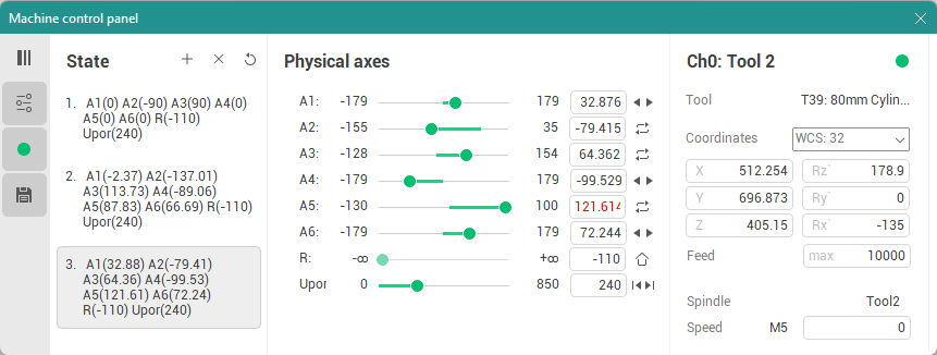
The State panel displays a list of stored states of the machine and a few buttons to control the elements of the list. Buttons have the following purpose.

- Add new state button adds the current machine state to the list.

- Delete selected state button deletes selected machine state from the list.

- Delete all states button removes all states from the list.
You can use double-click it in the list item to quick switch the machine to one of the stored states. Using the <Remember state> feature is helpful while constructing of manual transitions on machines with complex configuration of the axes (such as 6-axis articulated robots).
See also: