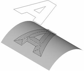
Job assignment for drive operations
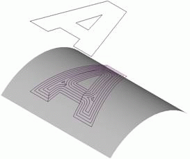
In the finish and roughfinish and rough drive operations the tool transition rule in a plane is defined by job assignment. The task for the user is to create a drive area, in a similar way as creating an area for the engraving and pocketing operations. The drive area formed by the curves can be dynamically displayed in green in the graphic window.
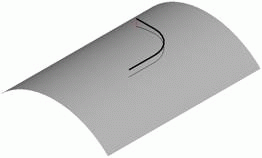
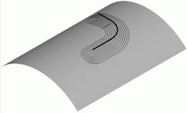
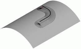
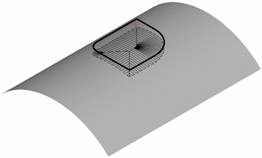
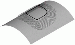
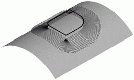
There are two main types of tool movement in the drive operations: along or across the curves of the drive area. When machining along drive curves, the shape of the toolpath is created as an offset of the drive curve. When machining across the drive curve, the paths are created perpendicular to the drive curves. The side of the curve, on which the machining is performed is defined by the type of the drive curve. In the following chart, there are examples on how drive curves and their types affect the machining strategy.
|
Drive Curve type |
Toolpath when machining along the drive curve |
Toolpath when machining across the drive curve |
|
Ditch |
|
Not recommended |
|
Ridge |
|
|
|
Cavity |
|
|
|
Ledge |
|
|
|
Outer curve – cavity, Inner curve – ledge |
|
|
If no curve is defined on the drive curves tab, then the drive area will be calculated by the system. The default method of area calculation depends on the type of drive operation.
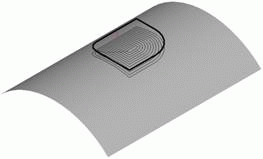
In the default for the drive roughing operation, the drive curve will take the shape of the outer border of the workpiece. So, if for example the shape of the workpiece is a box, then the drive curve will be a rectangle, and machining will be performed inside the rectangle and either parallel or perpendicular to its sides.
For the drive finishing operation, the default drive curve the system will use is the outer border of the model being machined, constructed using the method described in the Outer borders projection chapter.
For drive rest milling, by default the drive area is calculated so that machining is performed along the unfinished areas. For this purpose, first, the system detects the areas with residual material, and then the obtained area will be finished. Machining can be performed either along or across the unmachined areas.
See also:
