G-code based operation, G-code based lathe operation
|
Set NC program |
|
Select the interpreter |
|
Press "Run" |
|
Get the toolpath |
|
|
… |
|
… |
|
… |
|

< G-code based operation > ![]() and < G-code based lathe operation>
and < G-code based lathe operation> ![]() operations located in <Auxiliary> list. It can be also used for indexed and continuous processing at 4 and 5 coordinate machining centers. All available simulation types are supported, including additive manufacturing to simulate material layer buildup.
operations located in <Auxiliary> list. It can be also used for indexed and continuous processing at 4 and 5 coordinate machining centers. All available simulation types are supported, including additive manufacturing to simulate material layer buildup.
Note:
 < G-code based operation > does not support the turning tool.
 < G-code based lathe operation > supports only turning tool.
Both operations do not support Wire EDM machining.
These operations allow you to perform:
direct control of the machine simulation using G-codes;
check and optimize the NC program;
convert the text of the NC from one controller to another (for machines with identical kinematic scheme);
debug your own interpreter during its creation.
The toolpath is formed on the basis of the following operation parameters:
Specified NC text on the
 < Job assignment > parameters panel;
Selected interpreter on the
 < Strategy > parameters panel;
Assigned tool on the
 < Tool > parameters panel.
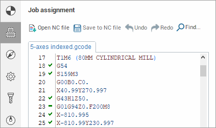
![]() < The NC text > can be written manually or can be loaded from an external file and edited, if necessary. The built-in text editor supports syntax highlighting of the main key structures of the CNC programming language, as well as a wide range of keyboard shortcuts for working with text.
< The NC text > can be written manually or can be loaded from an external file and edited, if necessary. The built-in text editor supports syntax highlighting of the main key structures of the CNC programming language, as well as a wide range of keyboard shortcuts for working with text.
More detailed information about the possibilities of working with the NC text is described in the section < Job assignment for G-code based operation, G-code based lathe operation >
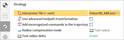
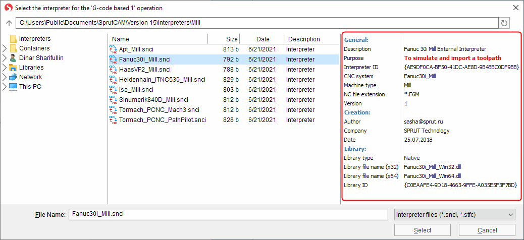
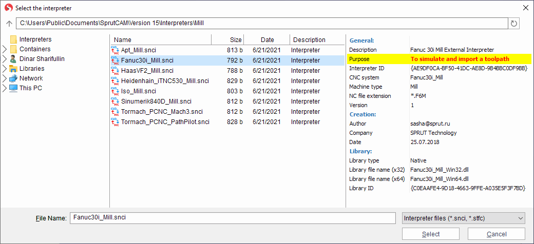
![]() < Interpreter file (*.snci) > defines the format of recognition of the controller commands in blocks of the NC program. The corresponding parameter specifies the full path to the selected interpreter. The parameter value can be entered manually as well as by using the file selection dialogue, which is accessed by using the
< Interpreter file (*.snci) > defines the format of recognition of the controller commands in blocks of the NC program. The corresponding parameter specifies the full path to the selected interpreter. The parameter value can be entered manually as well as by using the file selection dialogue, which is accessed by using the ![]() entered button. During the selection process, selection process, a preview of the interpreter information is available (description, purpose, CNC system, authors, etc.):
entered button. During the selection process, selection process, a preview of the interpreter information is available (description, purpose, CNC system, authors, etc.):
The ability to select an interpreter from the container is supported.
Currently, interpreters of the following CNC systems are available for use:
|
Machine group |
CNC system |
Comment |
Note |
|
Milling |
APT |
Import toolpath only |
|
|
Apt_Simplify_3D |
Import toolpath only |
|
|
|
ISO |
Import toolpath only |
|
|
|
Fanuc 30i |
To simulate and import a toolpath |
|
|
|
Haas VF-2 |
To simulate and import a toolpath |
|
|
|
Heidenhain iTNC 530 |
To simulate and import a toolpath |
|
|
|
NC210 |
To simulate and import a toolpath |
An additional license is required |
|
|
Sinumerik 840D |
To simulate and import a toolpath |
|
|
|
Tormach PCNC Mach3 |
To simulate and import a toolpath |
|
|
|
Tormach PCNC PathPilot |
To simulate and import a toolpath |
|
|
|
Global control |
Import toolpath only |
An additional license is required |
|
|
Turn-milling |
Sinumerik 840D |
To simulate and import a toolpath |
|
|
Okuma OSP-P300 |
To simulate and import a toolpath |
An additional license is required |
|
|
Robot |
Fanuc robot (R-30iB controller) |
To simulate and import a toolpath |
|
|
Kuka robot |
To simulate and import a toolpath |
|
|
|
Motoman robot |
To simulate and import a toolpath |
|
|
|
ABB robot |
To simulate and import a toolpath |
|
Note: All interpreters support command list generated by postprocessors in SprutCAM X distribution kit only.
"Import toolpath only" interpreters are not supported matching line NC code - trajectory of tool movement.
When you select an interpreter, pay attention to its purpose (the Purpose field in the Preview pane)
The selected interpreter should be intended for simulation. Otherwise, the trajectory of the tool may be incorrect (shifted relative to the coordinate system of the workpiece, duplicated approaches/retracts, incorrect starting position, etc.).
![]() < Use advanced toolpath transformation >-
this parameter converts the NC toolpath from machine to geometric.
Which, in turn, makes it possible to correct the toolpath using the robot axes map.
If the setting is disabled, then the final toolpath is formed (as closely as possible repeating the one specified in the NC program), without the possibility of changing it.
< Use advanced toolpath transformation >-
this parameter converts the NC toolpath from machine to geometric.
Which, in turn, makes it possible to correct the toolpath using the robot axes map.
If the setting is disabled, then the final toolpath is formed (as closely as possible repeating the one specified in the NC program), without the possibility of changing it.
![]() < Step of physic movements dividing > - available only when using Use advanced toolpath transformation (see above).
In this mode, at the first stage, the tool path is converted into a geometric curve. At the next stage, machine movements are rasterized with the step specified in the current parameter to ensure maximum similarity with the original toolpath. The smaller the value of the rasterization step, the higher the accuracy of construction and, accordingly, the similarity with the original toolpath.
< Step of physic movements dividing > - available only when using Use advanced toolpath transformation (see above).
In this mode, at the first stage, the tool path is converted into a geometric curve. At the next stage, machine movements are rasterized with the step specified in the current parameter to ensure maximum similarity with the original toolpath. The smaller the value of the rasterization step, the higher the accuracy of construction and, accordingly, the similarity with the original toolpath.
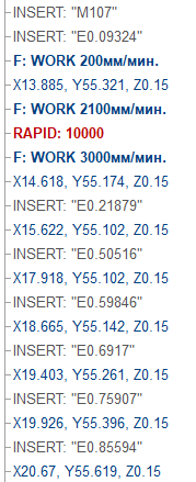
![]() < Add unrecognized commands in the trajectory > - this parameter
adds all commands of the control program not recognized by the interpreter to the toolpath. Unrecognized commands are added to the tool path description as a technology command parameter < INSERT > before the recognized commands.
< Add unrecognized commands in the trajectory > - this parameter
adds all commands of the control program not recognized by the interpreter to the toolpath. Unrecognized commands are added to the tool path description as a technology command parameter < INSERT > before the recognized commands.
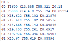
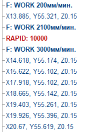
Example of how the parameter "Add unrecognized commands in the trajectory" works
|
NC program |
This parameter is disabled |
This parameter is enabled |
|
Commands M107, E - are not recognized by the interpreter |
|
|
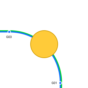
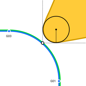
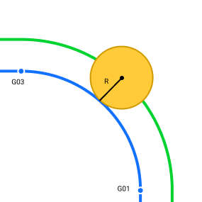
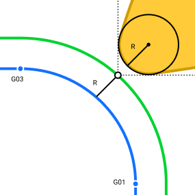
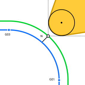
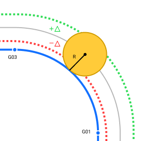
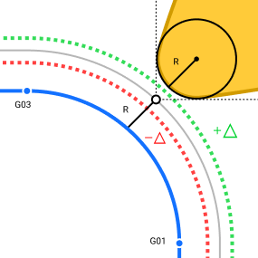
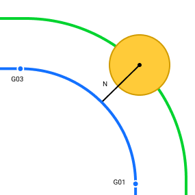
 < Radius compensation mode > - A
bility to disable or set an arbitrary compensation value on the tool radius.
< Radius compensation mode > - A
bility to disable or set an arbitrary compensation value on the tool radius.
|
Parameter value |
Milling |
Turning |
|
|
Radius compensation is disabled. |
Cutter radius compensation is disabled. |
|
|
Radius compensation is equal to the tool radius |
Cutter Radius compensation is equal to the tool nose radius |
|
|
Radius compensation is determined by the specified arbitrary value. |
Cutter radius compensation is determined by the specified arbitrary value. |

|
Parameter |
Milling |
Turning |
Note |
|
|
Additional tool offset. The total offset is calculated as the sum of the tool radius and the value of the additional offset. |
Additional tool offset. The total offset is calculated as the sum of the tool nose radius and the value of the additional offset. |
The setting is only available when using the |
|
|
Arbitrary value for radius compensation. |
Arbitrary value for cutter radius compensation. |
The setting is only available when using the |
![]() < The tool > that will be processed is determined on the corresponding tab of the operation parameters window. When creating G-code based operations, it is assigned a default tool for appropriate processing (milling or turning).
< The tool > that will be processed is determined on the corresponding tab of the operation parameters window. When creating G-code based operations, it is assigned a default tool for appropriate processing (milling or turning).
Note: Currently, the tool number indicated in the NC text is not taken into account when selecting from the list of project or library tools. Due to the above feature, only the NC text in which the processing is carried out by one tool can be assigned as a job assignment for each such operation.
G-code based operation demo video
See also:
Job assignment for G-code based operation, G-code based lathe operation
Keyboard shortcuts for working with NC text