Welding 5D and 6D operations
Welding 5D operation implements the functionality of automatic weld seam geometry calculation without reference to the particular type of welding equipment, ie it does not generate the specific commands to the laser, electric arc, gas burners, ultrasonic emitters etc.
Weld seam can be specified in the Job assignment window. The working process here is very similar to the curve definition in 5D Contouring operation.
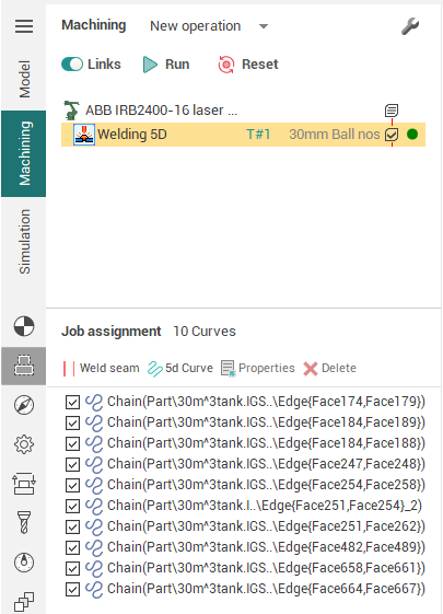
It is enough to add edge between welded parts and the system automatically calculates the angles for each point of curve such way that the weld head is held as close as possible to the middle between the adjacent walls but to not collide with them. Then the curve with tool vectors will appear in the screen. You can grab any of the vectors and drag it to the desired direction, when suddenly the angle counted automatically by the system, you do not like. At the same time dimensions will shown on the screen, by clicking on which you can enter exact values of tilt angles of the vector. To change the direction along curve just click on the blue arrow at the start of the curve. You can also drag the start and end points of the curve, by holding the appropriate marker.
In the properties inspector of the operation such properties can be found.
Lead and lean angles. Defines additional tool tilt to the side and along the curve for all curves specified in the job assignment.
Idling minimization. It affects the order of curve uniting, if there is more than one curve. If it is not enabled, the curves will follow in the order as they specified. Otherwise, the order can be changed to reduce the idle movements.
Arc interpolation. It reduces the number of frames in the NC code by combining short lines by arcs with a given accuracy. It is actual only if the machine supports spatial arcs (eg robots), because resulting arcs often lie in non-orthogonal planes.
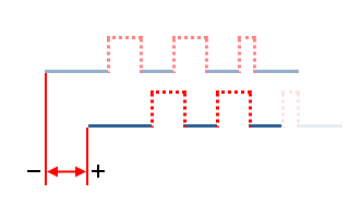
Extend (+)/Trim (-) passes. Allows to change (increase or reduce) the length of all defined curves without the need of start and end points dragging for each curve separately. By default has value of 50% of tool diameter (width of weld seam).
Engage/retract. Allows to define additional segment at the start or the end of each curve.
Safe motions, Safe surface and Links defines the type and sizes of links between curves.
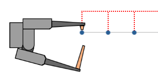
Then you can switch to the Simulation mode to see how the material is added to the place where the tip of the welding head is touching the workpiece. The thickness of the layer in simulation defined by the working length property of the tool, or if it is not set (more than the tool diameter), the thickness will equal to the tool diameter.
Welding 6d
In operation Welding 6d, the Welding type parameter is additionally available.
It supports the following w elding process type types:
 Seam welding
 Stitch welding
 Tack welding
 Spot welding

1
Seam welding
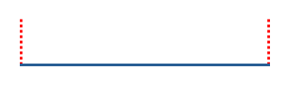
This is a continuous curved welding.
2
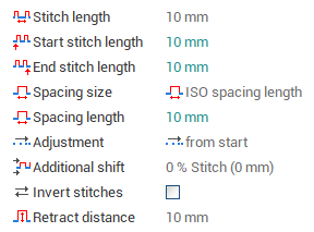
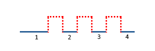
Stitch welding
It is intermittent. Сontains the following options:
|
|
|
|
|
|
|
|
|
|
|
|
|
|
||
|
|
|
|
|
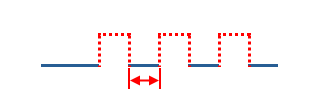
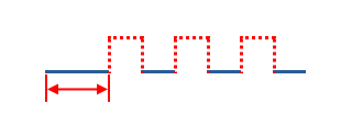
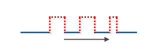
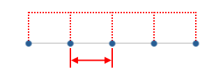
Sets the distance between the centers of strokes |
|
|
|
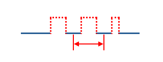
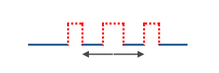
The number of strokes is set, spacings are distributed evenly over the remaining length. |
|
|
|
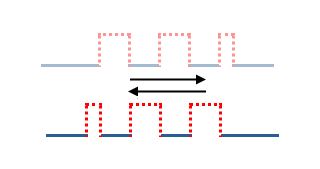
Alignment of stitches along the contour. |
||
|
|
|
|
|
|
|
|
|
|
|
|
|
|
|
|
|
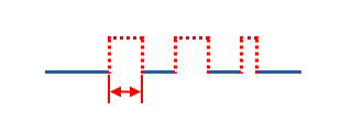
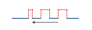
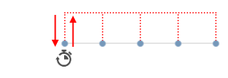
Additional displacement of stitches along the contour. |
|
|
|
Invert the distribution of stitches along the contour |
|
|
|
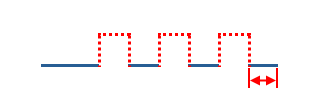
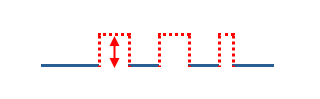
Distance of axial retraction from the contour at the transition between stitches |
|
|
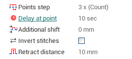
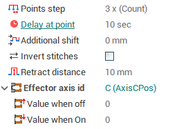
3 ![]() Tack welding
Tack welding
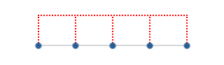
Tack welds are small and temporary welds used to hold parts together.
Сontains the following options:
|
Step between points |
|
|
Dwell time at each point in seconds. |
|
Other parameters are similar to Stitch welding
4
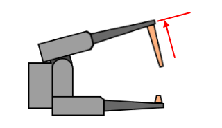
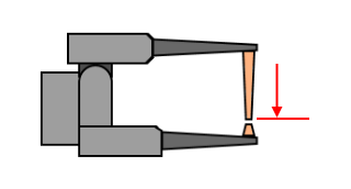
Spot welding
Сontains the following options:
|
ID of the machine axis, which is the axis of the working body - welding clamp |
|
|
|
|
|
|
|
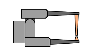
Other parameters are similar to Tack welding.
Effector On/Off command
This command turns welding on and off.
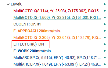
It is set if the simulation type is additive or paint according to the selected Effective Feeds. For additive operations and welding, the command is set to automatic.
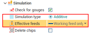
See also: