Job zones
Job zones are used to define the part and workpiece areas that have to be machined by roughing and finishing milling operations. Job zones can be closed and open. Open job zones first introduced in legacy SprutCAM offer an easy and intuitive way to define open machining areas using only source 3d model entities.
Using closed job zones
As a source geometry for closed job zones can be used closed chains of curves, edges and vertical walls. The best practice of using closed job zones includes the following steps.
In the graphic view select geometry entities defining the job zone. The easiest way is to use 3d Model edges. You can easily select the whole chain of tangent edges by simple double click on an edge of a chain.
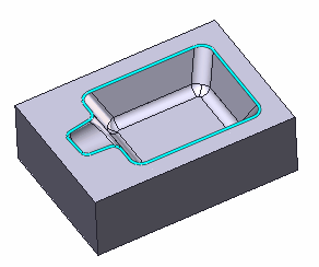
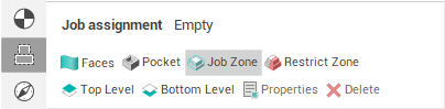
2. At the <Job Assignment> panel press the <Job Zone> button.

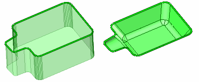
3. Doing so you will add a new <Job zone> into the <Job assignment> of an operation. According to the operation type a <Job Zone> may look different. There is the <Job Zone> for a <Roughing Waterline> operation at the left picture and the <Job Zone> for a <Finishing Drive> operation at the right picture following.
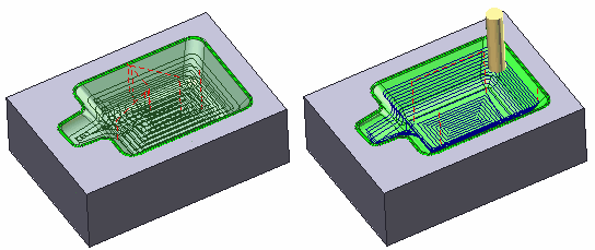
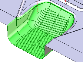
4. Generate toolpath. The trajectory should be contained inside the <Job Zone limits>.
Using open job zones
An open job zone is a half-space constructed by one or more entities. As source geometry for an open job zone you can use distinct curves, 3d edges and vertical walls as well as connected chains.
The best way to understand how and when to use open job zones is to look at practical examples.
Using open job zones in a roughing operation
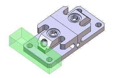
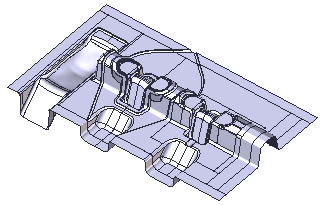
At the picture below you can see a complicated prismatic part consisting of many simple features. The workpiece for the part is a simple box. In the first stage we want to use a big tool to cut excessive material from the left side of the part using a roughing waterline operation.
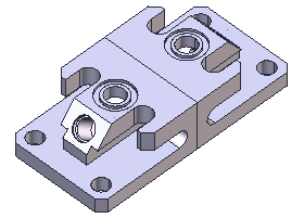
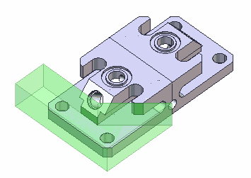
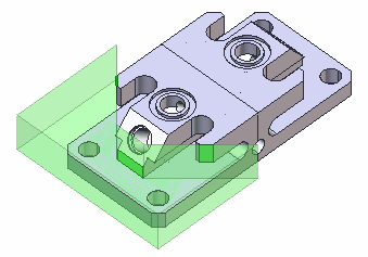
To accomplish this task and generate efficient toolpath without waste movements we have to define an open job zone, constructed from three vertical walls at the left side of the part. To do so we just consequently select the desired walls and add them into the Job assignment by pressing the <Job Zone> button at the <Job Assignment> panel.
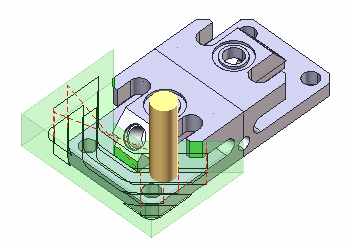
After that we generate toolpath. The result is depicted below:
Using open job zones in a finishing operation
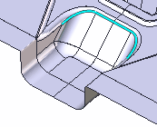
At the picture below you can see a die with three open freeform pockets. We will machine one small pocket using <Finishing plane> operation.
To accomplish this task we just need select the edge chain around the pocket and add it into the job assignment as a <Job Zone>.
After that we generate toolpath. The result should look as follows.
See also: