Thread milling cycle (W5DThreadMill(490))
Thread milling cycle is used to machine external or internal threading or to machine hole by a helix. Spiral machining is used then hole diameter is larger than the tool diameter. The tool rotates around the hole axis and simultaneously travels along the axis. spiral diameter is chosen according to the hole and the tool dimensions. Machining can be done in several passes to mill holes of desired diameter.
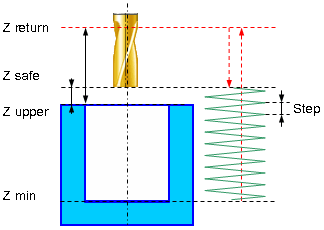
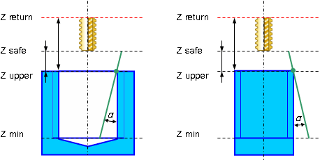
Spiral machining includes the following steps:
Rapid approach to the hole center at the <Z retract> level.
Rapid travel to the <Z safe> level.
Work feedrate travel to the spiral start.
Work feedrate spiral motion to the <Z min level>.
Optional circular pass on the bottom level. Circle diameter equals spiral diameter.
Return to the hole center.
Rapid travel to the <Z safe> level.
If additional roughing and finishing passes are applied previous five steps are repeated until desired hole diameter is reached.
Rapid travel to the <Z retract> level.
<Threadmilling> provides the following advantages over traditional tapping:
blind и through, left and right threads are machined by the same tool;
different threads with the same pitch are machined by the same tool;
all precision parameters are secured by the same tool;
accurate threading is machined to the full depth of the blind hole as the mill has no chamfer;
different materials are machined by the same tool;
high reliability of the machining because of good chip handling;
high efficiency of threadmilling due to higher cutting speed and feedrate;
low spindle torque even for coarse thread machining.
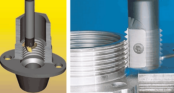
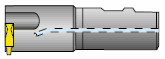
For threadmilling both single-cutter tools and multi-cutter ones allowing to machine several thread turns in one pass. Multi-cutter tool machining is much similar to spiral machining.
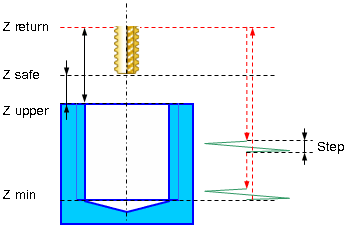
When using the multi-cutter tool threadmilling machining includes the following steps:
Rapid approach to the hole center at the <Z retract> level.
Rapid travel to the <Z safe> level.
Rapid travel to the tool cutting edge length distance which is determined by the number and size of the mill tooth size (thread pitch).
Work feedrate travel to the start of the spiral.
Machining along one spiral turn with step equaling thread pitch.
Retract to the hole center.
If one spiral turn is not enough to machine the threading to the full hole depth descend to the cutting-edge length and spiral motion are repeated until desired threading depth is reached.
Rapid return to the <Z retract> level.
If additional roughing and finishing passes are applied then the above steps are repeated until specified thread depth is achieved.
The spiral parameters panel defines the parameters for the spiral hole machining and thread milling.
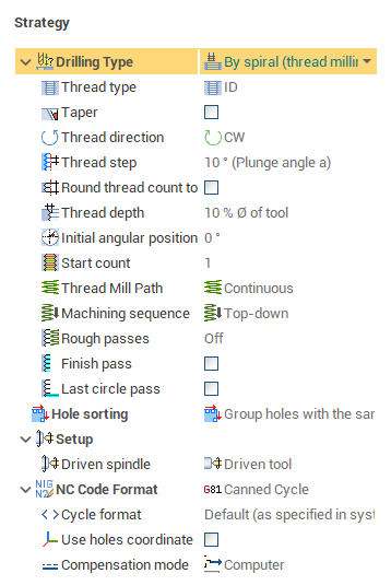
<Thread type> parameter specifies whether the threading is <External> or <Internal>.
There are cases when technology requires that threading is machined upside down and there are cases when threading is done from the bottom to the top. it defines in the <Machining sequence> field.
Thread kind, right or left, is determined by the <Thread spiral direction> parameter. For spiral machining it is convenient to define the spiral direction according to the spindle rotation direction. When <Follow> direction is specified the tool rotation and the spiral directions coincide, for the <Counter> direction they are opposite. The tool rotation is defined on the <Tool> page of the operation parameters dialog.
To machine the conical threads it is need to set <Taper angle> tick and specify the conic angle in degrees. The taper angle is measured from the top level of the hole (lug). Positive angle direction for tapered thread machining of the hole is the direction to the center of the hole. Positive angle direction for tapered thread machining of the lug is the direction from the center of the lug.
The <Spiral step> defines the spiral step for the spiral hole machining or the thread pitch in the case of the thread milling. If the <Plunge angle> mode is selected then the step is calculated with the using of the spiral angle, tool and hole diameters.
<Round turns count to integer> can be very useful for the spiral hole machining. If it is set then the step is recalculated to generate the integer coils number. The coil numbers is rounded to the nearest value to provide the required step. This option can not be used for the thread milling because it approximates the step.
<Last circle pass> specifies whether the circle motion is performed when the bottom of the hole is reached. if it is set then additional pass along the circle is performed on the bottom of the hole. The circle radius is equal to the spiral radius. This option must be disabled for the thread milling.
Multi-start thread is machined if <Thread start count> parameter is greater than 1. If start count is 1 single-start thread is machined.
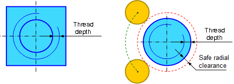
The <Thread depth> defines the distance between the inner and outer diameters of the thread. It works differently for the inner and outer threads. If hole is machined (inner thread), then the diameter that is defined in the job assignment defines the inner diameter of the thread. The outer diameter is calculated as the sum of the inner diameter and the thread depth. If the boss is machined (outer thread) then the diameter that is defined in the job assignment defines the outer diameter of the thread. The inner diameter of the thread is calculated as the difference between the outer diameter and the thread depth.
The <Thread depth> can be specified in current measurement units (mm or inch) on in the percents of the tool diameter.
In addition, for the correct machining of the external (OD) thread, it is need to specify the safe radial clearance value. It defines the radius at which the tool could safely bypass the boss if necessary.
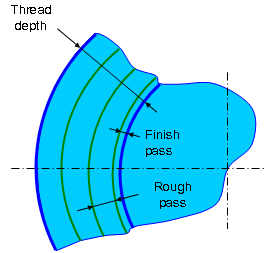
The thread milling can be performed in a few passes. Switch on the rough or/and finish passes to do it. If the <Finish pass> is checked the field near defines the stock for the finish pass. in this case the additional pass is generated before the last pass. The thread depth remained after the subtraction of the finish pass can be removed by rough passes. The step for the rough passes can be defined by a few ways:
<Off.>. the rough passes are not performed. So the all stack is removed in one pass.
<Distance>. The step is defined by the absolute value (mm or inches).
<% D of tool>. The step is defined in the percents of the tool diameter.
<Count>. The step is specified by the pass count. In this case the step is equal the thread depth divided into the count.
The <Lead in / Lead out> field allow to select the way of approach to the starting point or retract from the end point. The option has following items:
<Direct>. For the case of internal machining the approach is direct from the center of the hole to the beginning of the working pass. In the case of external machining approach implemented by a straight line, which starting point is at the safe radial clearance distance from the outer diameter of the thread.
<By arc>. Approach by arc allows to get a smoother start and end of thread. Arc radius and angle can be specified in the appropriate fields at the same panel. Note that the radius can be negative. It may be necessary for smooth plunging in the case of external machining, if you want to get the curvature direction of the arc coincides with the curvature direction of toolpath.
<Path type> parameter is used defines the toolpath type according to the used tool type. It can be one of the following:
<Continuous>. This toolpath type is used for the single-cutter tool, which forms only one thread turn with each turn of the spiral. Geometrically the trajectory is a continuous spiral.

<Transition along the axis>. This type is used for multi-cutter tool which forms multiple thread turns for one turn of the trajectory spiral. The trajectory consists of subsequent spiral turns connected with rapid cutting-edge long transitions along the spiral axis.


It is need to use the continues path type for the spiral hole machining cycle
<Cutting edge length> is used only for <Transition along the axis> toopath type. It specifies the length of transitions between adjacent spiral turns. This value must be calculated as the thread pitch multiplied on the coils number that can be created by the tool per one spiral turn.

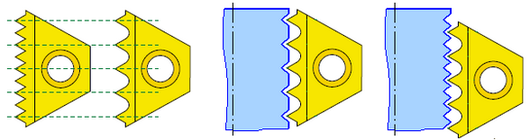
Fine pitch threads are threads with small pitches. It is difficult to produce multitooth inserts for small pitches because of the small radius between the teeth. It is developed inserts where every second tooth was dropped to enlarge the radius between the teeth. In this cases the tool needs to make a few coils. For example if the insert pitch is greater in two times than the thread pitch then two coils must be performed. The turn count defines it. In the most cases it's one, that means the insert pitch is equal to the thread pitch.
See also:
The ways of the holes machining