Tool 3D compensation
For the surface finishing operations it is possible to output to the G-code the normal vector of the surface at the point of contact with the tool. This allows to perform the so-called “3D compensation”, i.e. slight displacement of the tool at each point of the path away from the part.
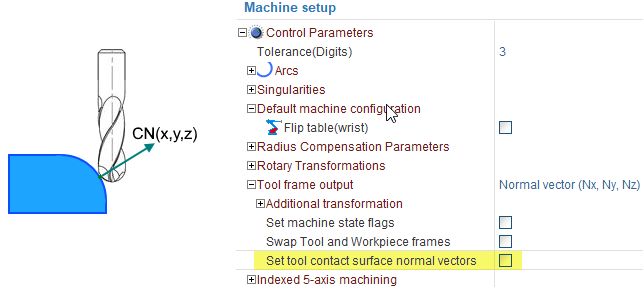
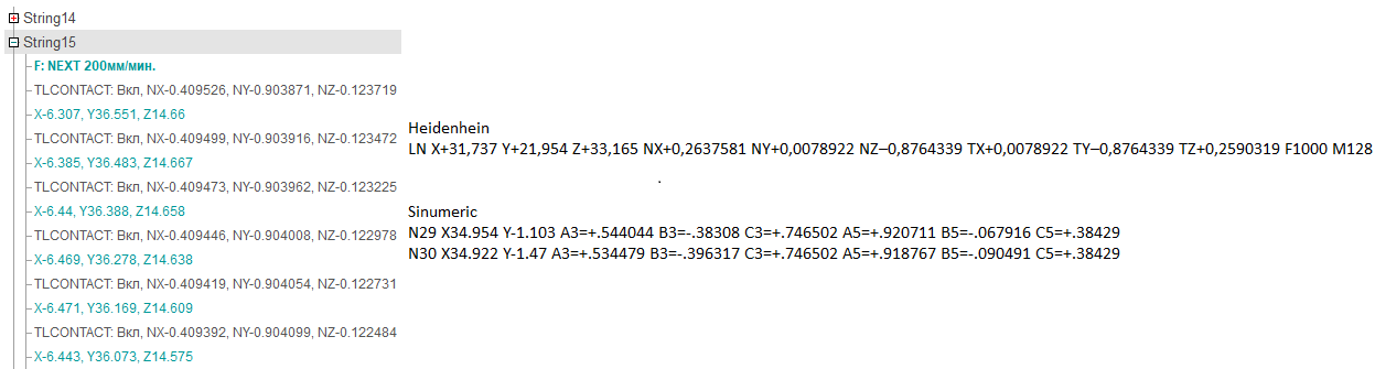
You need to enable the "Set tool contact surface normal vectors" flag in the settings of the machine schema in order to see this information in a G-code. In this case, a new TLCONTACT command (NX, NY, NZ) will appear in CLData for each path point, which contains the necessary normal vector for subsequent path points. In the postprocessor, depending on how 3D correction is supported in a particular CNC, you need to either directly output the contact normal to the G-code frame or manually shift each point of the path in the direction of this vector by the correction amount.