Multiaxis circle movement <MULTIARC>
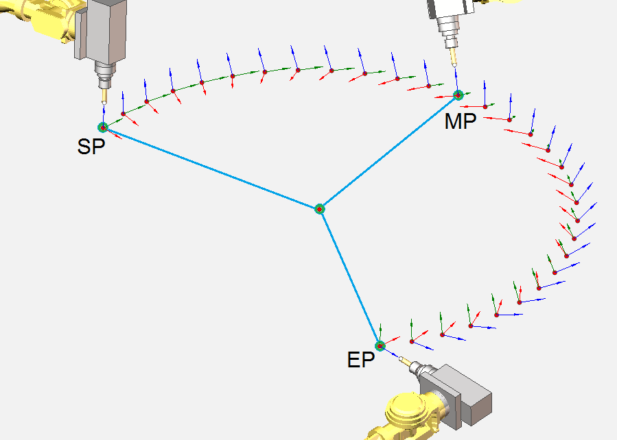
<MULTIARC> movement command defines a circular arc passing through three points with a predetermined orientation of the tool in space for each of these points. The figure below SP - starting position in which the tool was before running the command, MP - an intermediate position of the tool at the arc, EP - end position of the tool.
Command:
MULTIARC EPX ep.X, EPY ep.Y, EPZ ep.Z, EPRX ep.Rx, EPRY ep.Ry, EPRZ ep.Rz, EPRW ep.Rw, MPX mp.X, MPY mp.Y, MPZ mp.Z, MPRX mp.Rx, MPRY mp.Ry, MPRZ mp.Rz, MPRW mp.Rw)
Parameters:
|
Параметр |
Описание |
||
|
ep.X |
CLD[1] |
CLD.EPX |
Cartesian coordinates X, Y and Z of the arc end point |
|
ep.Y |
CLD[2] |
CLD.EPY |
|
|
ep.Z |
CLD[3] |
CLD.EPZ |
|
|
ep.Rx |
CLD[4] |
CLD.EPRX |
The parameters defining the orientation of the tool at the end point of the arc relative to the current coordinate system (fields RX, RY, RZ and RW). Depending on the configuration of the system (defined in the scheme of machine), the tool orientation can be specified by:
|
|
ep.Ry |
CLD[5] |
CLD.EPRY |
|
|
ep.Rz |
CLD[6] |
CLD.EPRZ |
|
|
ep.Rw |
CLD[7] |
CLD.EPRW |
|
|
mp.X |
CLD[8] |
CLD.MPX |
Cartesian coordinates X, Y and Z of the arc intermediate point |
|
mp.Y |
CLD[9] |
CLD.MPY |
|
|
mp.Z |
CLD[10] |
CLD.MPZ |
|
|
mp.Rx |
CLD[11] |
CLD.MPRX |
The parameters defining the orientation of the tool at the intermediate point of the arc relative to the current coordinate system (fields RX, RY, RZ and RW). Depending on the configuration of the system (defined in the scheme of machine), the tool orientation can be specified by:
|
|
mp.Ry |
CLD[12] |
CLD.MPRY |
|
|
mp.Rz |
CLD[13] |
CLD.MPRZ |
|
|
mp.Rw |
CLD[14] |
CLD.MPRW |
|
Parameters available through the Cmd operator
|
TCLDMultiArc: ComplexType |
Moving in a circular arc command defined by three points in space. |
||||
|
EndPos: ComplexType |
Cmd.Ptr["EndPos"] - structure whose fields identify the location of tool at the end point of the circle. |
||||
|
Axes: Array, Key="AxisID" |
Cmd.Ptr["EndPos.Axes"] - An array of structures such as Axis. One command may include movement along several axes, the position of each is stored in this array. |
||||
|
Axis: ComplexType |
Cmd.Ptr["EndPos.Axes"].Item[Index] or Cmd.Ptr["EndPos.Axes(<AxisName>)"] - Separate element of the Axes array. Contains information about moving on one machine axis. Access to the array elements can either by index or by key field. Here <AxisName> - the key field value, which must match the AxisID field value. |
||||
|
AxisID: String |
Cmd.Str["EndPos.Axes(<AxisName>).AxisID"] - The identifier of the machine axis, for which the specified new position. Determined by the machine schema. |
||||
|
Value: Double |
Cmd.Flt["EndPos.Axes(<AxisName>).Value"] - The new position of the machine axis, in which it moves. |
||||
|
Pos5D: ComplexType |
Cmd.Ptr["EndPos.Pos5D"] - structure containing the coordinates that define the final position of the tool in space. Determines not only the position of the tuning point of the tool (the fields X, Y and Z - cartesian coordinates), but also the orientation of the tool relative to the current coordinate system (fields NX, NY, NZ and NW). Depending on the configuration of the system (defined in the scheme of machine), the tool orientation can be specified by:
|
||||
|
X: Double |
Cmd.Flt["EndPos.Pos5D.X"] - X cartesian coordinate of the tool tip position. |
||||
|
Y: Double |
Cmd.Flt["EndPos.Pos5D.Y"] - Y cartesian coordinate of the tool tip position. |
||||
|
Z: Double |
Cmd.Flt["EndPos.Pos5D.Z"] - Z cartesian coordinate of the tool tip position. |
||||
|
NX: Double |
Cmd.Flt["EndPos.Pos5D.NX"] - depending on the system configuration may be the NX component of the tool normal vector, the rotation angle around one of the coordinate axis, or the coefficient of the quaternion. |
||||
|
NY: Double |
Cmd.Flt["EndPos.Pos5D.NY"] - depending on the system configuration may be the NY component of the tool normal vector, the rotation angle around one of the coordinate axis, or the coefficient of the quaternion. |
||||
|
NZ: Double |
Cmd.Flt["EndPos.Pos5D.NZ"] - depending on the system configuration may be the NZ component of the tool normal vector, the rotation angle around one of the coordinate axis, or the coefficient of the quaternion. |
||||
|
NW: Double |
Cmd.Flt["EndPos.Pos5D.NW"] - if you have chosen a method of orientation tool in the form of a quaternion is a fourth coefficient of quaternion. |
||||
|
MachineStateFlags: Integer |
Cmd.Ptr["EndPos.MachineStateFlags"].Bit[i], i=(0..31). Integer number which is a bit field of 32 bits from 0 to 31. If there are several variants for the location of the machine axes, providing a specified position of the tool in space, every bit of this field determines the selection of one of the possible solutions. For example, a five-axis machine with A and C axes for most of the positions of the tool has two possible solutions - with a positive A-axis and with negative value of the A axis. Zero bit of this field will choose one of these solutions. For a standard six-axis articulated robot many of the tool positions in space can be provided with different combinations of three of its key joints positions (the base, elbow and wrist joints) giving a total of 8 possible solutions. In this case, the zero bit in this field will determine the position of the base, the first bit - the position of the elbow, and the third bit will be set the position of the robot's wrist. Thus, the meaning of each of this bits is determined entirely by the used machine schema. When using machines that do not need to use these flags, it is possible to disable the output of this parameter to CLData in the machine scheme. |
||||
|
MidPos: ComplexType |
Cmd.Ptr["MidPos"] - structure whose fields identify the location of tool at the intermediate point of the circle. |
||||
|
Axes: Array, Key="AxisID" |
Cmd.Ptr["MidPos.Axes"] - An array of structures such as Axis. One command may include movement along several axes, the position of each is stored in this array. |
||||
|
Axis: ComplexType |
Cmd.Ptr["MidPos.Axes"].Item[Index] or Cmd.Ptr["MidPos.Axes(<AxisName>)"] - Separate element of the Axes array. Contains information about moving on one machine axis. Access to the array elements can either by index or by key field. Here <AxisName> - the key field value, which must match the AxisID field value. |
||||
|
AxisID: String |
Cmd.Str["MidPos.Axes(<AxisName>).AxisID"] - The identifier of the machine axis, for which the specified new position. Determined by the machine schema. |
||||
|
Value: Double |
Cmd.Flt["MidPos.Axes(<AxisName>).Value"] - The new position of the machine axis, in which it moves. |
||||
|
Pos5D: ComplexType |
Cmd.Ptr["MidPos.Pos5D"] - structure containing the coordinates that define the final position of the tool in space. Determines not only the position of the tuning point of the tool (the fields X, Y and Z - cartesian coordinates), but also the orientation of the tool relative to the current coordinate system (fields NX, NY, NZ and NW). Depending on the configuration of the system (defined in the scheme of machine), the tool orientation can be specified by:
|
||||
|
X: Double |
Cmd.Flt["MidPos.Pos5D.X"] - X cartesian coordinate of the tool tip position. |
||||
|
Y: Double |
Cmd.Flt["MidPos.Pos5D.Y"] - Y cartesian coordinate of the tool tip position. |
||||
|
Z: Double |
Cmd.Flt["MidPos.Pos5D.Z"] - Z cartesian coordinate of the tool tip position. |
||||
|
NX: Double |
Cmd.Flt["MidPos.Pos5D.NX"] - depending on the system configuration may be the NX component of the tool normal vector, the rotation angle around one of the coordinate axis, or the coefficient of the quaternion. |
||||
|
NY: Double |
Cmd.Flt["MidPos.Pos5D.NY"] - depending on the system configuration may be the NY component of the tool normal vector, the rotation angle around one of the coordinate axis, or the coefficient of the quaternion. |
||||
|
NZ: Double |
Cmd.Flt["MidPos.Pos5D.NZ"] - depending on the system configuration may be the NZ component of the tool normal vector, the rotation angle around one of the coordinate axis, or the coefficient of the quaternion. |
||||
|
NW: Double |
Cmd.Flt["MidPos.Pos5D.NW"] - if you have chosen a method of orientation tool in the form of a quaternion is a fourth coefficient of quaternion. |
||||
|
MachineStateFlags: Integer |
Cmd.Ptr["MidPos.MachineStateFlags"].Bit[i], i=(0..31). Integer number which is a bit field of 32 bits from 0 to 31. If there are several variants for the location of the machine axes, providing a specified position of the tool in space, every bit of this field determines the selection of one of the possible solutions. For example, a five-axis machine with A and C axes for most of the positions of the tool has two possible solutions - with a positive A-axis and with negative value of the A axis. Zero bit of this field will choose one of these solutions. For a standard six-axis articulated robot many of the tool positions in space can be provided with different combinations of three of its key joints positions (the base, elbow and wrist joints) giving a total of 8 possible solutions. In this case, the zero bit in this field will determine the position of the base, the first bit - the position of the elbow, and the third bit will be set the position of the robot's wrist. Thus, the meaning of each of this bits is determined entirely by the used machine schema. When using machines that do not need to use these flags, it is possible to disable the output of this parameter to CLData in the machine scheme. |
||||
|
Time: Double |
The time of the movement in minutes. |
||||
The list of coordinates passed through CLData is defined by the SprutCAM machine scheme.
See also: