Lathe grooving cycle G74, G75 <LATHEGROOVE>
Cycle <LATHEGROOVE(402)> implements the G74 cylindrical grooving canned cycle and G75 face grooving canned cycle. Groove shape is rectangular and is defined by its dimensions: width and height. The cutting is done by consequent work passes of the tool with Z and X axes stepping.
Parameters:
|
Description |
||
|
CLD[1] |
CLD.SubCmd |
Command type: ON(71) – canned cycle on, CALL(52) – canned cycle call, OFF(72) – canned cycle off. |
|
CLD[2] |
CLD.SubType |
Canned cycle type identifier: LATHEGROOVE(402) |
|
CLD[3] |
CLD.CLParams(1) |
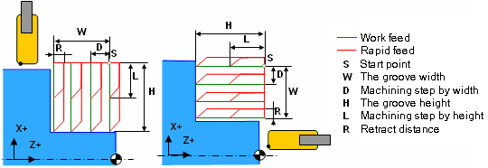
The groove type: 0 – turn groove (G75), 1 – face groove (G74) |
|
CLD[4] |
CLD.CLParams(2) |
The signed width of the groove measured relative to the start point (W) |
|
CLD[5] |
CLD.CLParams(3) |
The signed height of the groove measured relative to the start point (H) |
|
CLD[6] |
CLD.CLParams(4) |
The absolute amount of the machining step by width (D) |
|
CLD[7] |
CLD.CLParams(5) |
The absolute value of the machining step by height (chip breaking depth, L) |
|
CLD[8] |
CLD.CLParams(6) |
The absolute distance of the side retract before return of tool (R) |
|
CLD[9] |
CLD.CLParams(7) |
The absolute value of the lead out for chip breaking. |
|
CLD[10] |
CLD.CLParams(8) |
Delay at the bottom in seconds |
|
CLD[11] |
CLD.CLParams(9) |
Chip breaking mode:
|
If a "signed" parameter is positive it is laid off in the positive direction of respective axis, otherwise it is laid off in negative direction.
See also: