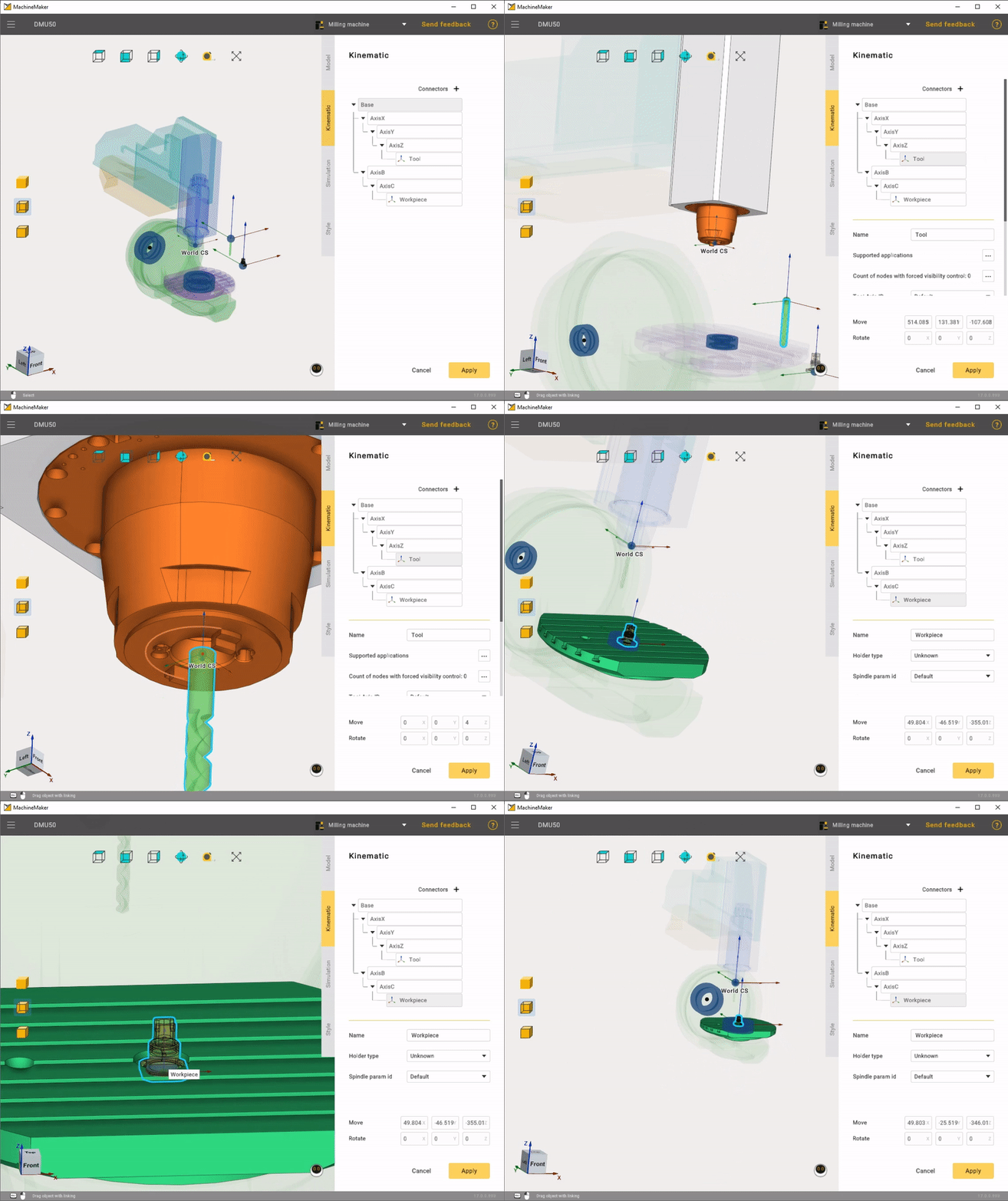
Building a kinematic scheme
Click Kinematic tab to open kinematic parameters panel.
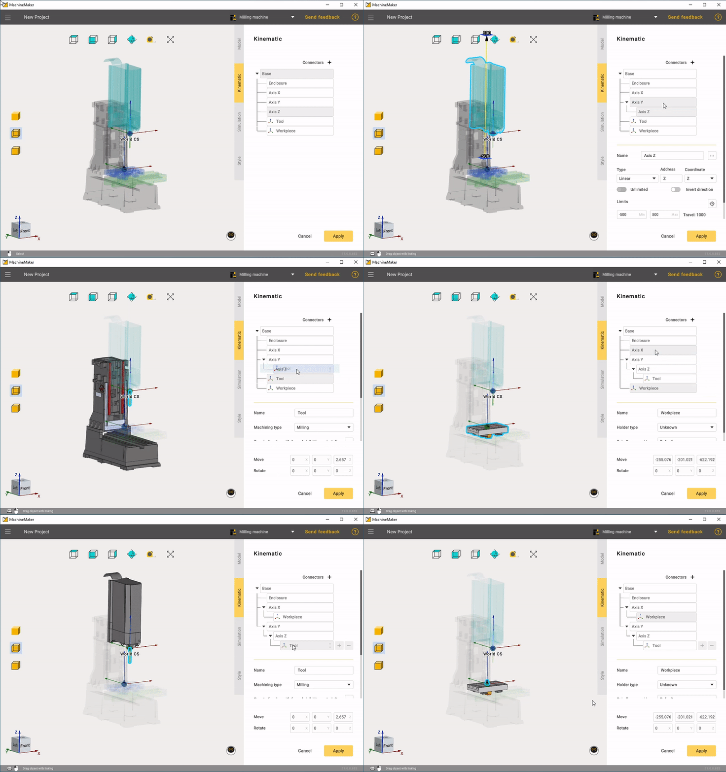
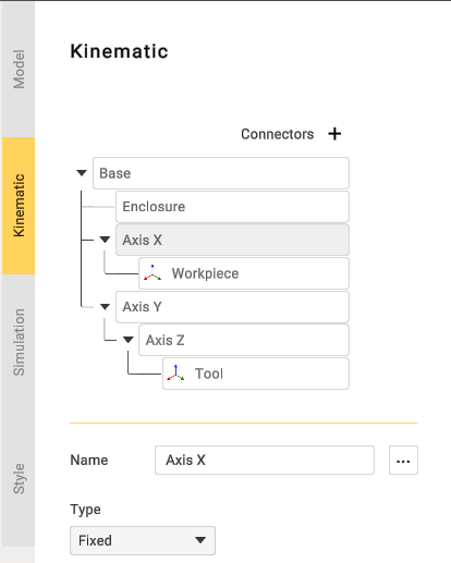
First of all it is necessary to build correct mechanism's kinematic tree, using grag and drop. MachineMaker will show Tool node as a sample tool and Workpiece node as a sample part.
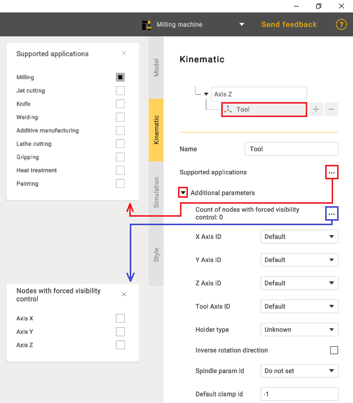
In the Tool settings there is a function to select Supported applications and also additional options.
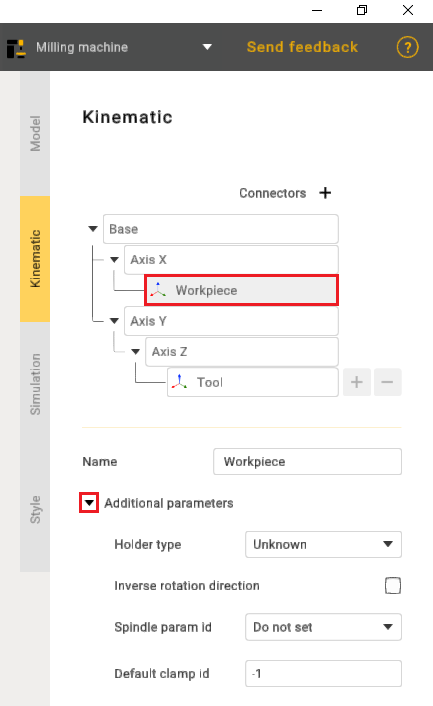
Workpiece also has its own additional parameters.
Next it is necessary to specify parameters ofeach node.
Set node name and type.
Next it is necessary to specify node Address for Linear and Rotary nodes. It will be used in Postprocessors.
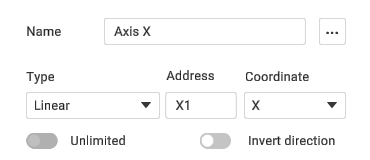
Select linear axis direction. You can select X Y Z or custom. Use Orientation field to define Custom direction vector.
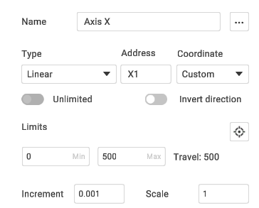
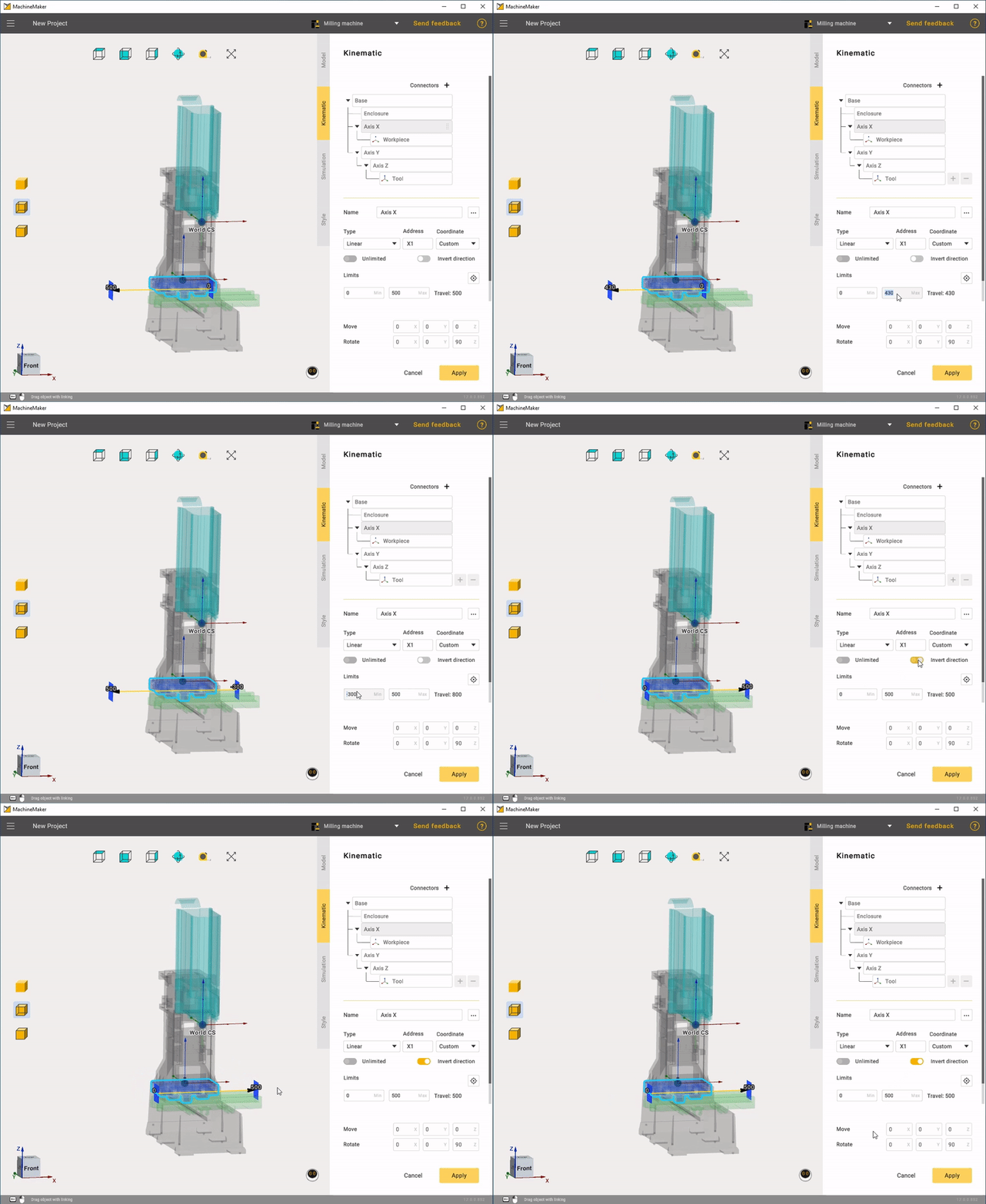
Next define Has Brake, Increment and Scale parameters. Change Control parameter if axis is Indexed or Manual. It is possible to Invert Direction of axis.

For rotary axes it is necessary to specify point of rotation. Hold the Left Mouse Button, drag the bearing and drop it to the snap point. Use Transformation Panel to set position and rotation manually.
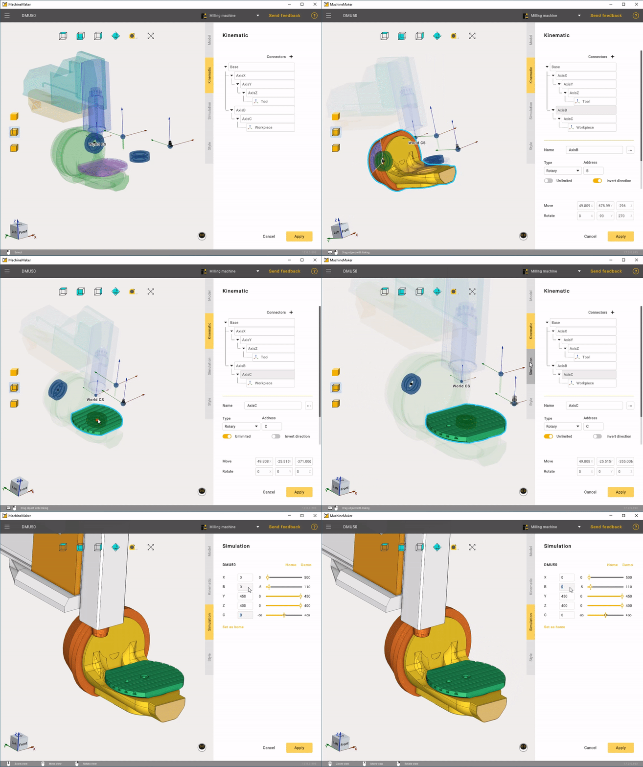
Finally it is necessary to set Tool Type and specify positions of Tool and Workpiece. Place Tool and Workpiece to the correct position at the Kinematic tree. Then hold the Left Mouse Button, drag the bearing and drop it to the snap point. Use Transformation Panel to set position and rotation manually.
