Assеmbly parameters
Click  button to open Assembly settings panel. Check SprutCAM documentation and SmartHints for parameters information.
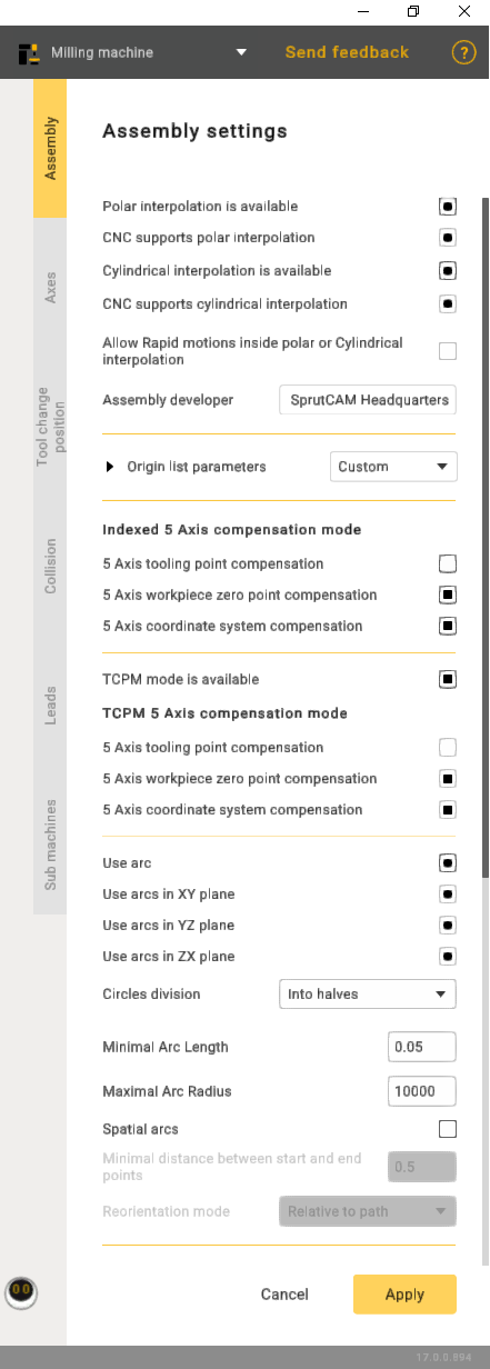
Polar interpolation changes a linear axis to the rotary one in the simple 3-axes milling process. Usually it is necessary on the lathes that has the drive mill tool. Sometimes the polar interpolation is used with another king of machines.
If the machine variable Machine –> Control parameters –> Rotary transformations –> CNC support polar interpolation is set then CNC interpolation tick is available. If this parameter is on then the G-code generated with the commands to switch on/off the polar interpolation. Else the G-code is generated in the [X,C,Z] coordinates.
The cylindrical interpolation gives the possibility to mill the side surface of cylinder by programming the unrolled curves. The unrolled curves are programmed in the [X,Y,Z] coordinates, but the cylinder milling is performed in [X,C,Z] coordinates. So the cylindrical interpolation makes the transformation [X,Y,Z] => [X,C,Z].
If the machine variable Machine –> Control parameters –> Rotary transformations –> CNC support cylindrical interpolation is set then CNC interpolation tick is available. If this parameter is on then the G-code generated with the commands to switch on/off the cylindrical interpolation. Else the G-code is generated in the [X,C,Z] coordinates.
Allow rapid motions inside polar or Cylindrical interpolation. This capability is crucial for improving efficiency in machining operations, as rapid motions reduce the time required to traverse from one point to another, enhancing overall machining productivity.
Assembly developer: Company name.
Indexed 5-Axis compensation mode represents a configuration in which compensation is systematically applied to a machining process involving five axes.
The 5-Axis tooling point compensation feature implies the CNC controller's capability to dynamically adjust the tool's position or orientation throughout machining, accommodating variations in the tool itself. This ensures precise adherence of the machined part to the intended design.
5-Axis workpiece zero point compensation guarantees the correct alignment of machining operations with the workpiece's coordinate system, enhancing precision and accuracy in the manufacturing process.
The 5-Axis coordinate system compensation ensures that the CNC machine accurately interprets and executes toolpaths, considering the specific orientation and location of the workpiece in the machining space. This feature is pivotal for achieving precision and accuracy, especially when dealing with intricate geometries, and allows for versatile machining operations.
TCPM mode availability refers to the availability of a concept in CNC machining where the tool's center point is efficiently managed, ensuring precise and accurate machining.
TCPM in the 5-Axis compensation mode, refers to a feature in CNC machining where adjustments are made to account for variations in the tool's center point. In a 5-axis setup, which allows movement in five different directions, this compensation mode ensures precise and accurate machining by dynamically managing the tool's center point.
The 5-Axis tooling point compensation within the context of TCPM refers to a feature in CNC machining where adjustments are made to the tool's position or orientation dynamically.
The 5-Axis workpiece zero point compensation, in conjunction with TCPM, is a feature in CNC machining that involves dynamic adjustments to align machining operations accurately with the zero point or origin of the workpiece coordinate system. In a 5-axis machining system, capable of movement along five directions, this compensation mechanism ensures precision and accuracy during the manufacturing process.
The 5-Axis coordinate system compensation, when integrated with TCPM in CNC machining, is a functionality designed to ensure precise toolpath execution by dynamically adjusting for the specific orientation and location of the workpiece within the machining space.
Use arc function provides users with the capability to specify or enable the use of arc commands in the CNC program. It involves defining parameters such as the arc's start and end points, radius, and direction.
Circles division: Used to divide arcs into halves or quarters.
Minimal Arc Length: Prevents the output of arcs shorter than a specified length; a segment will be displayed instead.
Maximal Arc Radius: Prevents the output of arcs with a radius larger than specified; segments will be displayed.
Spatial arcs: Arbitrary spatial arcs. A function necessary for robots to work.
Minimal distance between btart and end points: A restriction that allows the display of segments with a small distance between points.
Spatial arcs. A function necessary for robots to work.
Reorientation mode: The method of calculating the midpoint. The functionality may vary depending on the manufacturer.