Descent types in plane roughing operations
In the plane roughing and drive operations, it is possible to limit a tools downward movement. The limitations may be based on the peculiarities of the cutting tool or due to hard machining of the workpiece that can only cut into material at a limited angle.
One of the following descent types can be used:
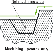
<Machining strictly upwards>. Tool movement down inside the material being machined is absolutely restricted. The material, left in hollows will not be machined. Such a method is advised for use on convex models. A model that has hollows or pockets will require subsequent rest milling.

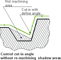
<With the defined maximum cutting angle> – without machining of shadowed areas. If necessary, the tool may move down, but within the defined angle. The material, which is left in hollows, will not be machined. Consequently, details with abrupt walls in hollows will require rest milling. The maximum cutting angle must be set within 0 (similar to machining strictly downwards) and 90 degrees (like without control).

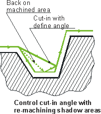
<With the "defined maximum cutting angle with machining of shadow areas"> the tool, as in the previous case, can cut into the workpiece material within the defined angle, but the material remaining in hollows will subsequently be removed. Machining is performed using reciprocal moves with simultaneous plunging at the defined angle. The maximum descent angle must be more than zero.

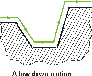
<Without descent control>. The tool movement direction is not controlled. The machined detail may contain unmachined areas because of the tool geometry.

The descent type for the plane roughing and drive operations can be assigned in the <Strategy> page.
See also: