Robot axes map
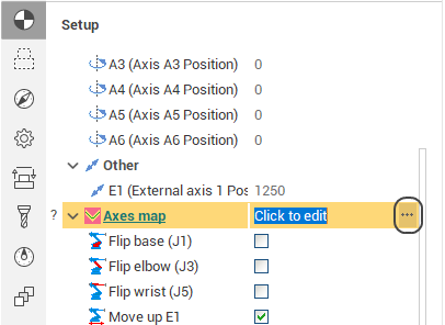
The Robot Axes Map allows to define manual and fine-tune automatic control laws for the excessive degrees of freedom of a robot (the 6th axis, the rails axes, the rotary table axes). The feature is available at the Operation Setup by pressing the ellipsis button next to the Robot axes map parameter.
The feature is available in the following SprutCAM X configurations:
Robots
Master
Pro
Remark: need additional "Advanced robots" module licence.
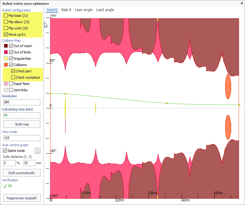
Robot configuration
First you have to choose the robot configuration/state to be used in the operation. It's the same configuration/state that you can edit in the Operation Setup under the Robot Axes Map parameter. The robot configuration is defined by the "Flips" - the alternative positions of robot's joints (base, elbow, wrist) which allow the same position of the tool relative to the workpiece - and the modes of positioning of excessive axes such as rails and rotary tables (Move Up E1, Rotate E2).
Optimized axis
In the Optimized Axis combobox you select the axis that you define the control law for at the moment.
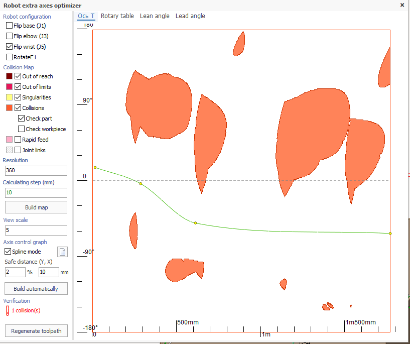
Collision map
Collision map is the visual representation of collision zones in the toolpath. Along the X axis is the position of the tool on the toolpath from the beginning measured by length. Along the Y axis is the value of the optimized axis. The following types of collisions are detected.
Out of reach zones (maroon) are zones which the robot can not reach.
Out of limits zones (purple) are zones which the robot can reach but some of the robot's axes go out of its' defined limits.
Singularity zones (yellow) are zones where the robot's joints move at extreme speeds.
Collision zones (orange) are zones where the robot parts collide with each other or with the workpiece.
The map resolution can be set in the Resolution box as the amount of steps along the Y axis to be calculated.
To build or refresh the map hit the Build map button.
Check part and workpiece
Under the 'Collisions' checkbox there are 2 checkboxes for specifying whether part and/or workpiece are accounted for in the collision detection. They are enabled only if the parent 'Collisions' checkbox is set to 'True' . It is advisable to switch them depending on the type of machining - cutting, additive machining, or welding.
Axis control spline
The axis control law is defined as a spline curve. By default there is no spline. It means the optimized axis value either stays the same (in manual mode) or is controlled automatically (in the automatic mode) for the entire toolpath (the horizontal gray dashed line).
The goal is to create the nicest curve possible that passes through the collision-free white zone from left to right.
To create a new spline double-click on points in the empty space the spline has to pass through. Two points is enough. After the spline is created you can change it's shape by dragging the spline control points with the mouse, by deleting the control points (by right clicking on a point) or adding new points (just pull the spline with the mouse).
Use the Clear button to erase the spline.
Use the Build automatically button to build the collision avoiding spline automatically.
Verification
In this area the status of the current toolpath is displayed. If there are no collisions in the toolpath the green Ok is displayed, if there are any collisions, the number of collisions is displayed in red. The status is updated every time you change the axis control spline.
At the same time in the graphic view the collision zones in the actual toolpath curve are also marked with thick strokes of the corresponding collision type color.
You can either click on the empty space in the axes map or move the mouse while holding the left mouse button to position the tool to the corresponding position of the toolpath.
Regenerate toolpath
To apply the axis control law to the toolpath click the Regenerate toolpath button.
The Robot Axes Map is available for robots as a part of the additional 'Robot +' module for SprutCAM X's configuration:
By default:
Robot
As option:
5x Mill*
Master*
Pro*
* - the additional 'Robot +' license for support robots is needed.