Chamfering
This operation generates a chamfering trajectory on specified edges, chamfers or fillets from the 3D model. It is most often used as the finishing for edge beveling or for deburring along the edges of the part that were formed after milling. The operation allows to machine chamfers and at the same time not to damage the part where there are no chamfers. Cylindrical end mills, conical mills, spherical mills are available for chamfering.
Job assignment
In this operation, it is possible to handle chamfers both present on the 3D model and defined using sharp edges.
![]()
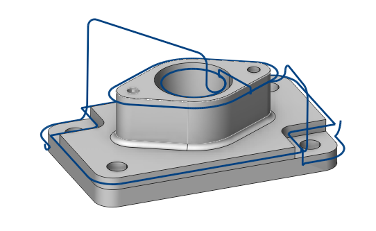
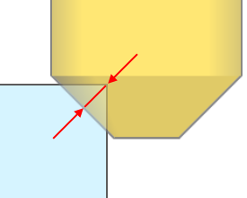
To machine chamfers based on edges, you need to add them using the “Add Sharp Edge” button on the “Job assignment” tab. If you select a face instead, then all sharp edges of this face are automatically added.
![]()
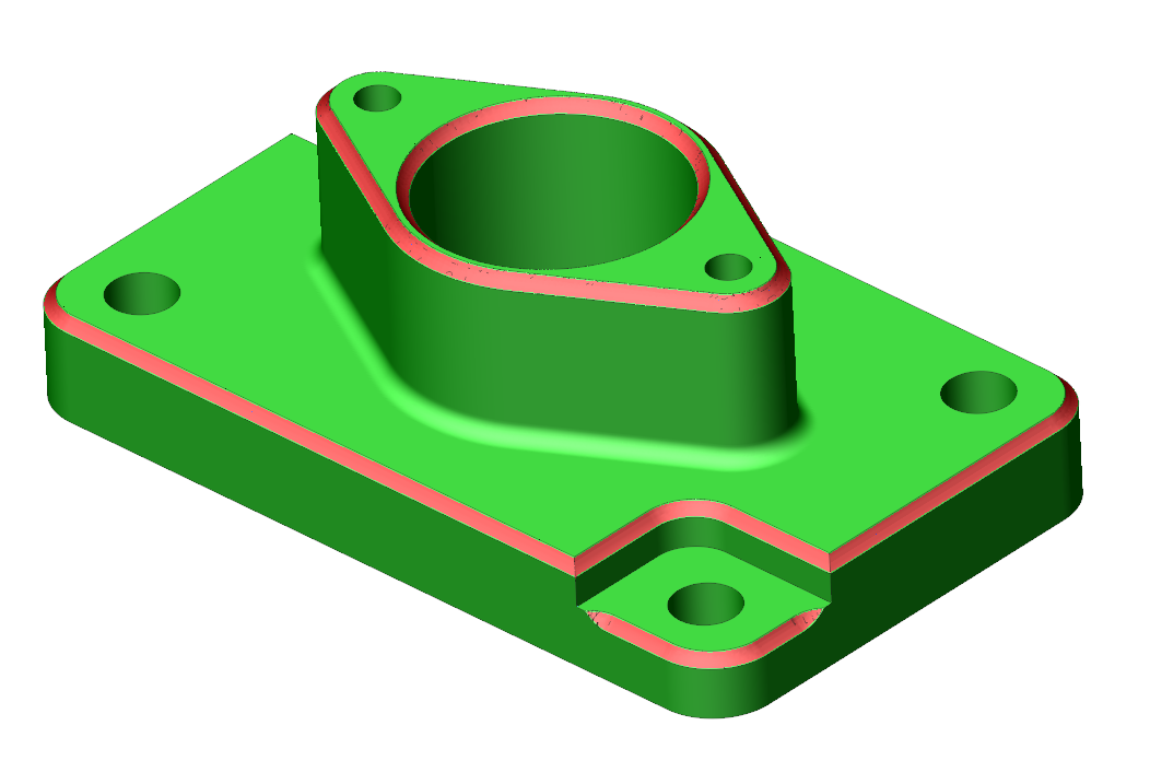
To machine chamfers which are present on a 3D model, you need to select faces marked as chamfers and add them using the “Add Face” button.
![]()
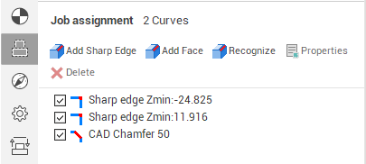
It is also possible to automatically recognize and add chamfers using the “Recognize” button.
Chamfer types
For convenient use chamfers can be one of the four types:
 Sharp edges
 CAD chamfers
 Fillets
 Hole chamfers
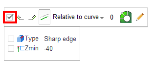
To highlight chamfers with similar parameters, you can use the auxiliary panel in the graphics window that appears when a job assignment curve is selected.
Main parameters of the operation
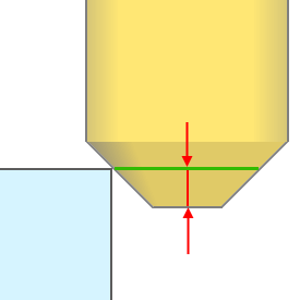
Chamfer depth
Specifies how far the tool will plunge into the part. If a “CAD Chamfer” is machined, then the tool passes over the surface of the chamfer.
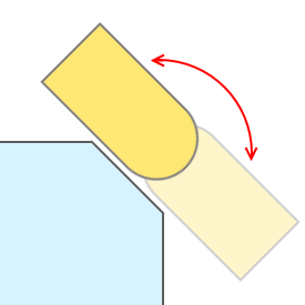
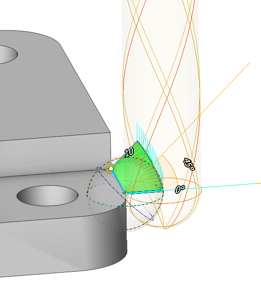
Incline tool
This parameter allows tilting the tool to chamfer with its side.
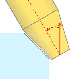
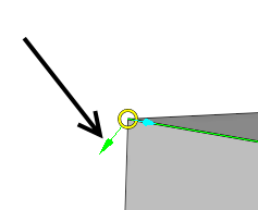
Tool contact point
It is the point on the tool with which it should mainly touch the geometric objects specified in the job assignment of the operation. The contact point is determined by the distance from the tool tip. It can also be changed interactively in the graphics window.
Inverse tool axis direction
This parameter appears only when the "Incline tool" option is enabled. It allows you to machine the chamfer at a different angle to the axis of the tool.
The same effect can be achieved by changing the side if clicked on the direction arrow in the graphics window. In this case, the direction of the tool axis changes for each curve individually.
Overlap
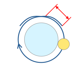
Allows extending the trajectory in closed chamfers so that there are no burrs left at the junction.
Interactive tuning
In some special cases, you may need to change the normal of the plunge into the part. To do so, you can use the interactive normals that appear when you select the job assignment curve in the graphics window.