FBM Machining Procedure
The FBM procedure is a machining sequence defined either for a feature or a feature class. There are two types of FBM procedures.
Atomic procedures
Complete procedures.
The Atomic procedure does only a small part of machining. Usually it consists just of one operation. The examples of atomic procedures include Spot Drilling, Rough Drilling, Chamfer Sinking, Chamfer Contouring.
The Complete procedure includes all the operations needed to machine a feature completely.
When you select a procedure for a feature in the UI only complete procedures are suggested to you. When you add operations to a selected procedure, only the atomic procedures are suggested.
A FMB procedure consists of four parts.
The procedure metadata such as type (atomic, complete), caption, icon, last modification date.
The Feature Constraints.
The Tool Query List
The Operation List
Feature Constraints
The Feature Constraints is the part that defines what type of a feature is the procedure for and what parameters should the feature meet.
The examples of feature types include Hole, Stepped Hole, Hole Groove.
Every feature type has its own set of parameters. For instance, a hole has such parameters as type (blind, through), diameter, height, tip angle, taper angle and others. A stepped hole is a composite feature. It consists of two or more holes and may include some grooves. A hole groove is a cutout in a hole that is defined by such parameters as type (round, square, trapezoid), height, diameter, taper angle, corner radius
In the Feature Constraints you define the constraints for the parameters the feature has to satisfy in order to be applicable to the machining procedure. The constraints can be expressed in the following ways.
Just a value. E.g. Diameter=10.
A range of values (Min..Max). E.g. Diameter=10..20.
Less Than (<) expression. E.g. Diameter<5.
Less Or Equal (<=) expression. E.g. Diameter<=5.
Greater (>) expression. E.g. Diameter>5.
Greater Or Equal (>=) expression. E.g. Diameter>=5.
When the user selects a feature in the UI to assign a machining sequence for it, SprutCAM X scans through all procedures in the library and compares the feature against the feature constraints of every procedure. Every time it finds a match the procedure is added to the suggestion list. After that SprutCAM X looks at the Tool Query Lists of the procedures and searches for the tools in the Tool library.
Tool query list
The Tool Query List consists of entries defining the rules of selection of the tools from the Tool Library for the operations of the machining procedure.
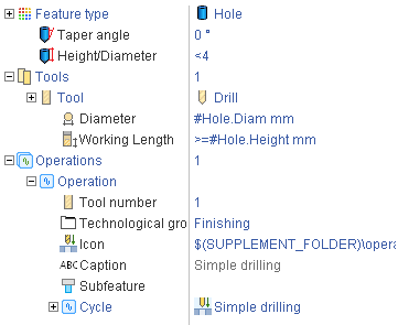
For each tool query the desired tool type and the constraints for the tool parameters are specified. The tool parameters constraints are expressed the same way as the feature constraints. The important thing is it is possible to use the references to the feature parameters in the tool constraints. A reference is defined by the full path to the parameter started with the # character. For example, for a hole feature the possible parameter references include #Hole.Diameter, #Hole.Height, #Hole.TipAngle and others. So for a hole machining procedure a usual tool query looks like:
Tool.Type = Drill;
Tool.Diameter=#Hole.Diameter;
Tool.Length>=#Hole.Height.
It is possible also to use math operators and math functions in the constraints. For example, for a chamfer machining operation the tool query has the following constraints:
Tool.Type = Conical Mill
Tool.TaperAngle = Hole.TipAngle/2.
Operation list
The operation list is the list of machining operations to be used with the feature.
For every operation the following parameters are defined:
Subfeature Id.
Tool number.
Technological group.
Icon and caption.
Machining cycle type.
Machining cycle parameters.
The Subfeature Id is the Id of the subfeature of a composite feature which this particular operation machines. For example, a Stepped Hole machining procedure consists of operations that machine particular steps and grooves of this hole, so Subfeature Id of its operations can be Step1, Step2,...StepN, Groove1, Groove2,.. GrooveN.
The Tool number specifies the number of the tool in the Tool Query List which the operation uses. Several operations can use the same tool. In this case they will have the same tool number.
The Technological Group defines the class to which the operation belongs. There are the following technological groups:
preparing;
roughing;
semi-finishing;
finishing;
completive
The Machining cycle type sets the machining cycle for the operation. For every feature type there are numerous machining cycles available. For example, for a hole feature there are such cycles as Simple Drilling, Drilling w/Chip Breaking, Drilling w/Chip Removing and others available.
The Machining cycle parameters are stored as a list of pairs Parameter=Value, so only the important parameters has to be specified, the other parameters will have the default values of the cycle.