Common principles of technology creation
To calculate a toolpath and generate a CNC code in SprutCAM one need define input data at first: select the machine, which the part will be produced with and specify the geometric models of the part, the stock and the fixtures. Than he should form a machining sequence and specify the parameters of machining operations. Next the system calculates the toolpath and adds all the needed technology commands to get an NC-program that meets all prescribed requirements.
The machining sequence in SprutCAM is organized into a hierarchical tree with operations as nodes. Basic node of the tree is an <Operation>. In particular the operation is determined strategy of parts working and combine in oneself set of parameters, that is individual for every type of machining. To bring an order into the machining sequence the operations groups that can contain the other operations are introduced.
A machining tree may have an arbitrary complexity to meet any certain requirements. An example of such a tree is shown below:
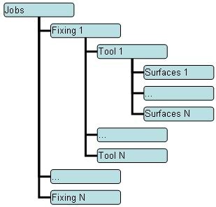
Here, the <Fixing> node contains actions performed on the workpiece in a fixed position. The <Tool> node contains actions performed with one specified tool. While the <Surfaces> nodes perform actions on concrete surfaces.
Every operation in SprutCAM has associated with it <Geometrical coordinate systems>, a <Tool>, a <Job assignment> etc. Therefore, each operation can represent the fixing, the tool and the surfaces nodes at the same time. This voids a false tree complication in simple cases. On the other hand, the tree structure of a machining sequence allows simply handle with sophisticated cases.
The task of a user is specification of the machining sequence up to the level of surfaces nodes. The further decomposition is performed by the system automatically while calculating a tool path for each operation. The generated tool paths depend on the operation type and the values of the associated with operation parameters. The operation type is specified once when creating a new operation, while the parameters values can be changed in any time. At that, parameters alteration involves toolpath regeneration.
The tool path at the bottom level is a sequence of the machine commands in the <CLDATA> format that include both the tool motion commands and the technological commands such as the feed rate switch, spindle and coolant switch on/off, etc. A tool path has a hierarchical structure like the machining tree: the elementary commands are united into the logical groups. The types and the contents of groups depend on the operation type. For example, the structure of the tool path of the <Plane roughing operation> is shown below:

The work on creating a machining sequence as well as defining its input data and specifying the parameters of operations is performed on the <Machining> tab.
See also:
Selection of a machine and its parameters definition
List of types of machining operations