Pick-and-place
Tool path and parameters
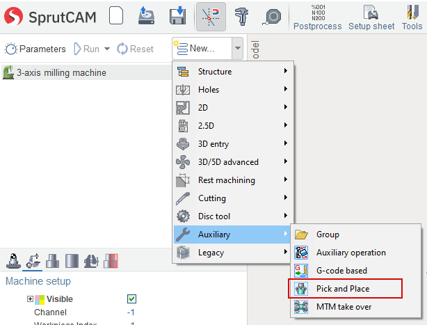
"Pick and place" operation is designed to control the gripper tool to move the workpiece inside the job zone of a machine.
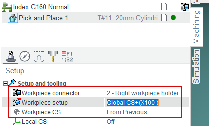
The workpiece is moved from the place, that was defined in the previous operation to the new place, that is defined by Workpiece connector and workpiece setup. All movements of the gripper is generated in the defined workpiece coordinate system.
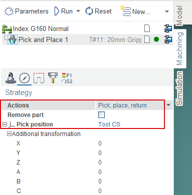
Tool path of pick and place operation has 3 main sections: pick, place, return.
Pick section contains the movement of a gripper from the initial position of the tool (usually tool change point) to the pick position of the part. Pick position is defined in geometry coordinate system with additional offsets.
Place section has the movements of gripper with the workpiece from the initial position to the new one. It can be executed via the safe surface or with the enabled collision avoidance option.
Return section is the movements of empty gripper from the place position to the final one (usually tool change point).
Actions parameter defines the sections that must be generated. If the option remove part is enabled then the workpiece disappears after the placing.
Machine requirements
The kind of machine-tool can be any: milling center, lathe with subspindle, industrial robot. The main requirement is the existing of the special tool holder that is marked as gripper. If gripper is absent in the current machine schema, then pick and place operation will not be available.
You can switch on this option on the machine setup page or in the file of machine schema description.
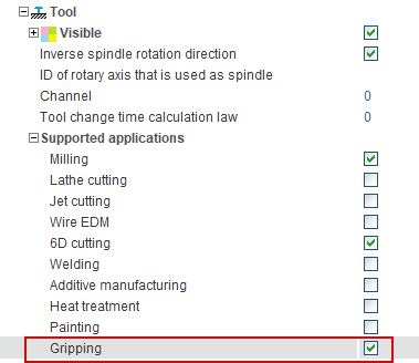
The fragment of the machine schema about the tool holder definiton is shown below. Note that the Gripper is enabled inside the SupportedToolTypes.
<SCType ID="MillSpindle" Caption="Mill Spindle" Type="TToolHolderNode">
   <VisualProperties>
       <Metallic DefaultValue="True"/>
   </VisualProperties>
   <XAxisID DefaultValue="AxisX"/>
   <YAxisID DefaultValue="AxisY"/>
   <ZAxisID DefaultValue="AxisZ"/>
   <SupportedToolTypes>
      <MillTool DefaultValue="true"/>
      <LatheCutter DefaultValue="true"/>
      <Gripper DefaultValue="true"/>
   </SupportedToolTypes>
</SCType>
Adaptation of the turn milling lathes with subspindle
Pick and place operation can be used to move the workpiece between the main spindle and subspindle on the turn-milling machines. To make it possible the subspindle must be declared as tool holder with the gripping application. If you have got the machine schema of turn milling machine with subspindle designed for the SprutCAM version 14 and earlier, then you need to modify the machine description. Below the differences between the old (left) and adapted (right) schemas is shown.
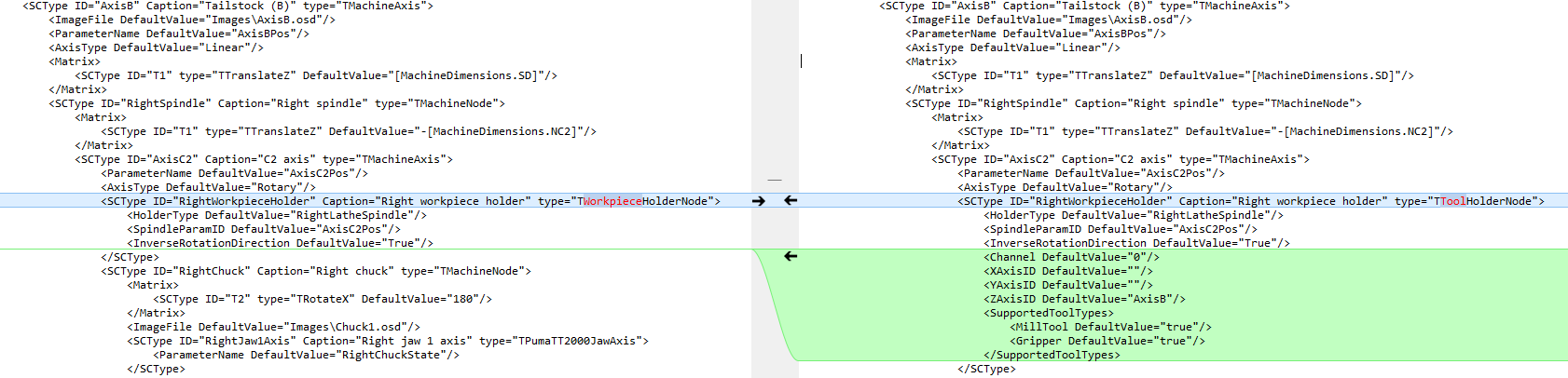
1. In the subspindle definition TWorkpieceHolderNode is replaced by TToolHolderNode.
2. XAxisID, YAxisID, ZAxisID - the names of the axes that is responsible for the motion of the tool along the correspondent axis are added.
3. Gripper is added into the SupportedToolTypes
Video below demonstrates how to make the assembling projects